
Control Parameter Optimizing System and Operation Control Optimizing Apparatus Equipped Therewith

a technology of operation control and optimization equipment, which is applied in the direction of electric controllers, program control, electric programme control, etc., can solve the problems of inability to support the various control panel specifications and diverse operational requirements, limited control parameters and improvement items

Active Publication Date: 2017-01-05
MITSUBISHI POWER LTD
View PDF0 Cites 9 Cited by
  • Summary
  • Abstract
  • Description
  • Claims
  • Application Information

AI Technical Summary

Benefits of technology

The present invention allows for better control of an existing plant's operation without needing to modify the control panel or equipment. This is useful for different types of plants and control panels.

Problems solved by technology

For this system, the control parameters and improvement items are limited.
Thus one problem with this optimum operation system is that it cannot support the various control panel specifications and diverse operational requirements in a one-size-fits-all manner; power plants having different control panel specifications or different operational requirements typically require their control panels or their equipment to be modified.

Method used


Image

  • Control Parameter Optimizing System and Operation Control Optimizing Apparatus Equipped Therewith
  • Control Parameter Optimizing System and Operation Control Optimizing Apparatus Equipped Therewith
  • Control Parameter Optimizing System and Operation Control Optimizing Apparatus Equipped Therewith

Examples


first embodiment

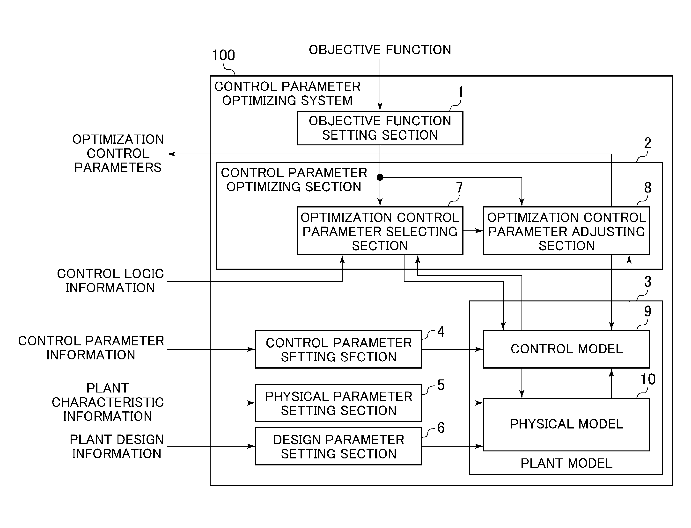
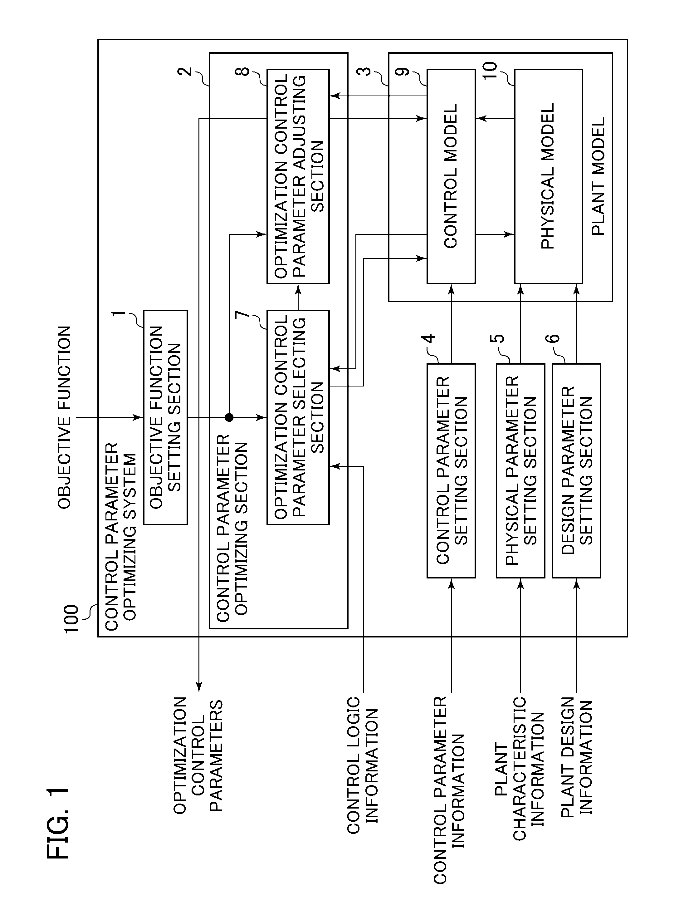
[0018]FIG. 1 is a block diagram showing a configuration of a control parameter optimizing system according to a first embodiment of the present invention. In FIG. 1, the control parameter optimizing system 100 includes an objective function setting section 1, a control parameter optimizing section 2, a plant model 3, a control parameter setting section 4, a physical parameter setting section 5, and a design parameter setting section 6.

[0019]The objective function setting section 1 sets the objective functions inputted by an operator to the control parameter optimizing section 2. The objective functions in this context are the improvement items for plant operation control (such as start-up time, rate of load change, equipment lifetime consumption, fuel cost, and generation efficiency, etc.); they are each defined by the function of a plant process amount. There may be one or a plurality of objective functions to be inputted to the objective function setting section 1. One way of inpu...

second embodiment

[0063]FIG. 6 is a block diagram showing a configuration of an operation control optimizing apparatus according to a second embodiment of the present invention. In FIG. 6, the operation control optimizing apparatus 101A differs from the operation control optimizing apparatus 101 according to the first embodiment (FIG. 3) in that the apparatus 101A further includes a plant operation limiting value calculating section 15 and an optimum solution selecting section 16.

[0064]The plant operation limiting value calculating section 15 calculates plant operation limiting values based on the plant characteristic information extracted by the plant characteristic information extracting section 203 and on the plant design information extracted by the plant design information extracting section 204. The plant operation limiting value calculating section 15 then outputs the calculated plant operation limiting values to the optimum solution selecting section 16. The plant operation limiting values in...


PUM


Abstract

A control parameter optimizing system and an operation optimizing apparatus equipped therewith are provided, the system being applicable to an existing plant without modifying the control panel or equipment of the plant, the system further being capable of optimizing the operation control of the plant in accordance with diverse operational requirements. The system includes an objective function setting section, a plant model, and a control parameter optimizing section. The control parameter optimizing section includes an optimization control parameter selecting section and an optimization control parameter adjusting section. The optimization control parameter selecting section selects as an optimization control parameter the control parameter for optimizing an objective function based on control logic information extracted from a power plant. The optimization control parameter adjusting section adjusts the value of the optimization control parameter using the plant model in such a manner as to optimize the objective function.

Description

BACKGROUND OF THE INVENTION[0001]1. Field of the Invention[0002]The present invention relates to an apparatus for optimizing the operation control of a power plant or an industrial plant.[0003]2. Description of the Related Art[0004]There have been developed control technologies for improving the plant operability, particularly of a thermal power plant. The technologies include those for enhancing load following capability or shortening start-up time, etc., to stabilize an electric power system in response to fluctuations in the supply of renewable energy or in the demand for power.[0005]JP-2007-255198-A discloses an optimum operation system which, used in an energy plant combining boilers, turbines and generators, determines the amount of steam generated by each boiler and the amount of steam and that of oil steam distributed to each turbine (the amounts are called control parameters) in such a manner as to minimize the total energy cost (improvement item) of the plant based on a ch...

Claims


Application Information

Patent Timeline
IPC IPC(8): G05B19/418G05B11/01G05B15/02
CPCG05B13/042G05B2219/32015G05B2219/37591G05B11/01G05B15/02G05B19/4183G05B19/41835
Inventor YOSHIDA, YASUHIROYOSHIDA, TAKUYASEKIAI, TAKAAKITOKUDA, YUYAYAMANAKA, KAZUNORIYAMASHITA, ATSUSHIIYANAGA, NORIHIRO
Owner MITSUBISHI POWER LTD
Learn More