Work Vehicle

Active Publication Date: 2017-01-05
KUBOTA LTD
View PDF50 Cites 8 Cited by
  • Summary
  • Abstract
  • Description
  • Claims
  • Application Information

AI Technical Summary

Benefits of technology

The present invention relates to a stepless speed changer device for vehicles, which is designed to efficiently cool the device using an air passage. The device includes a housing with an accommodation space for a drive pulley, a driven pulley, and an endless rotary body. The driven pulley side has a smaller number of objects that may interfere with air introduction, allowing a large amount of cooling air to be introduced. This air is then discharged through a first discharge opening to cool the device and reduce friction and wear. The discharged air is guided and blown through an air drawing opening to cool the engine oil in the oil pan of the engine. The housing has two additional discharge openings for balancing air intake and outlet and avoiding air flow reversal. The invention prevents dust and other objects from entering the device and allows it to cool more effectively while operating at higher temperatures. This results in a longer service life for the device and reduces the need for an oil cooler.

Problems solved by technology

However, with the above-described conventional technique, due to e.g. presence of a structural object(s) obstructive to the introduction of air into the accommodation space, there was a tendency of the amount of cooling air drawn into the accommodation space being relatively small.
For this reason, there would tend to occur shortage of amount of air in the air passage of the accommodation space, thus insufficient cooling of the stepless speed changer device.

Method used


Image

  • Work Vehicle
  • Work Vehicle
  • Work Vehicle

Examples


Embodiment Construction

[0049]Next, an embodiment of the present invention will be explained.

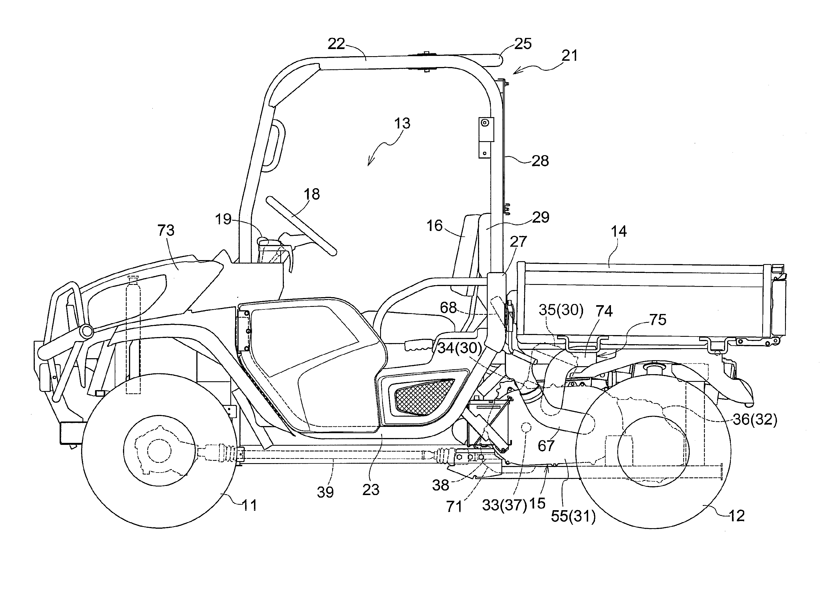
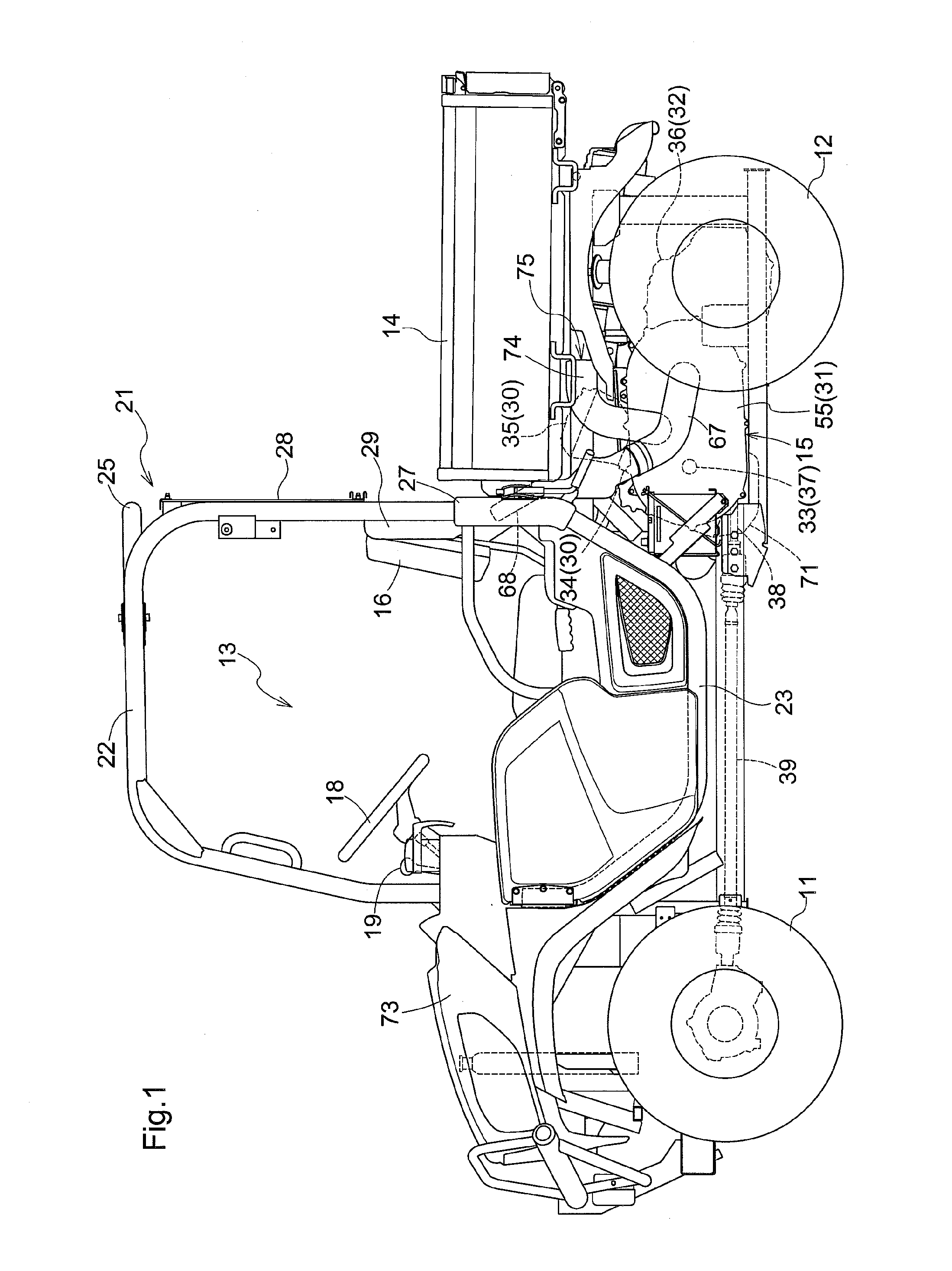
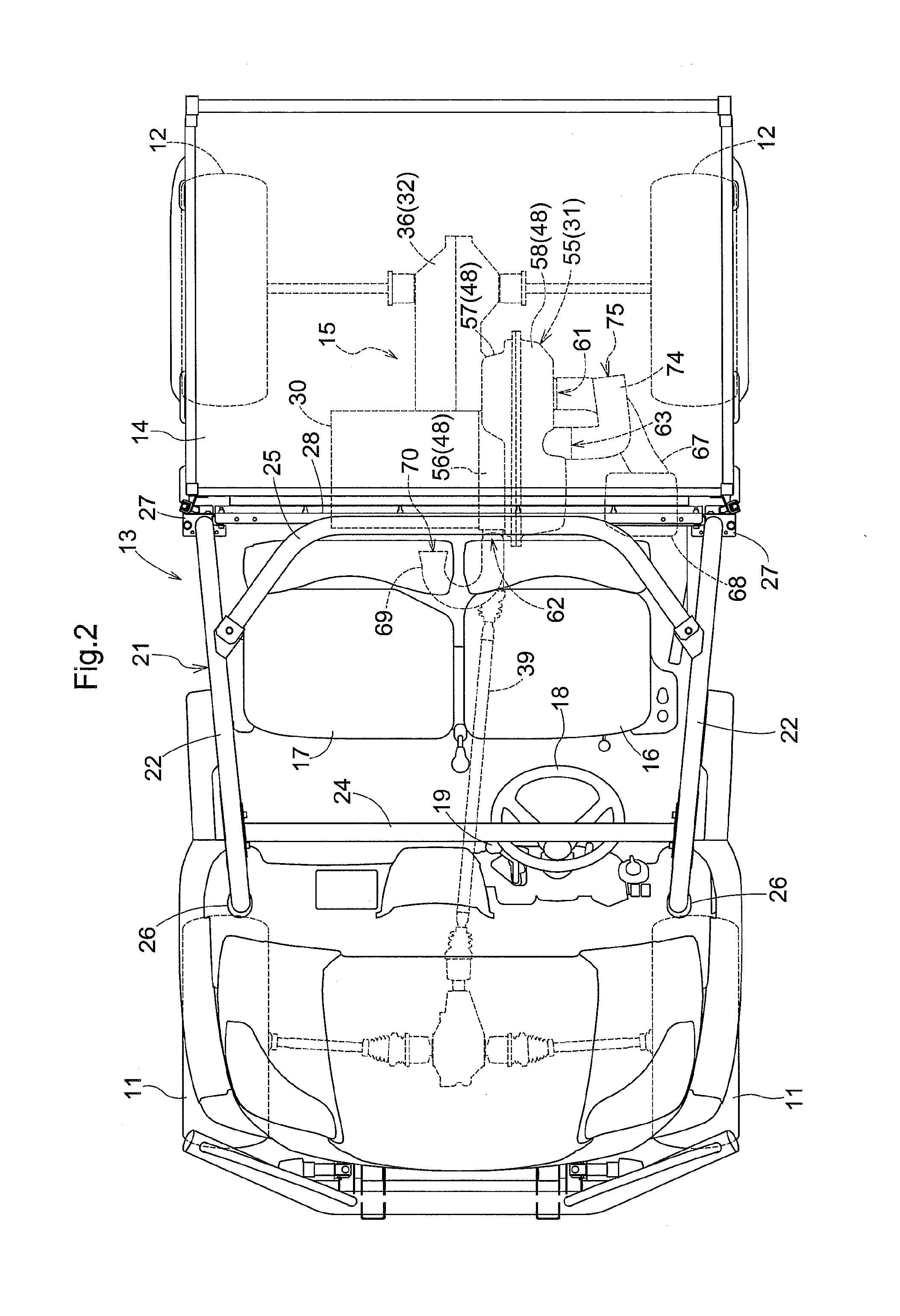
[0050]A multi-purpose vehicle (an example of “work vehicle”) shown in FIG. 1 and FIG. 2 is a vehicle for multiple purposes such as load transporting, leisure activity, etc. This multi-purpose vehicle includes a pair of left and right steerable and drivable front wheels 11, a pair of left and right drivable rear wheels 12, and a traveling vehicle body that can travel by the left and right front wheels 11 and the left and right rear wheels 12. At a front-rear center portion of the traveling vehicle body, a driving section 13 is provided. Rearwardly of the driving section 13 of the traveling vehicle body, a load-carrying platform 14 is provided. Downwardly of the load-carrying platform 14 in the traveling vehicle body, an engine section 15 is provided.

[0051]In the driving section 13, there are provided a driver's seat 16 at which an operator can be seated, an auxiliary seat 17 at which a passenger can be seated, a ste...


PUM


Abstract

A work vehicle includes a stepless speed changer device having a drive pulley receiving input of power of an engine, a driven pulley, and an endless rotary body wound around and entrained between the the drive pulley and the driven pulley and an accommodating body having an accommodation space for accommodating the drive pulley, the driven pulley and the endless rotary body. The accommodation space includes an air passage for causing air introduced from the outside to flow from the driven pulley side to the drive pulley side to be eventually discharged to the outside.

Description

CROSS-REFERENCE TO RELATED APPLICATION[0001]This application claims priority to Japanese Patent Application No. 2015-133949 filed Jul. 2, 2015, the disclosure of which is hereby incorporated in its entirety by reference.BACKGROUND OF THE INVENTION[0002]Field of the Invention[0003]The present invention relates to a work vehicle.[0004]Description of the Related Art[0005]A conventional work vehicle is disclosed in e.g. Japanese Unexamined Patent Application Publication No. 2012-51505. The conventional work vehicle includes a stepless speed changer device having a drive pulley (“a drive rotary body” in this document) receiving input of power of an engine, a driven pulley (“a driven rotary body” in the document), and an endless rotary body wound around and entrained between the the drive pulley and the driven pulley. The work vehicle further includes an accommodating body (“a “speed changer case”, etc. in the document) having an accommodation space for accommodating the drive pulley, the...

Claims


Application Information

Patent Timeline
IPC IPC(8): F16H57/027F16H57/035F16H9/18
CPCF16H9/18F16H57/027F16H57/035
Inventor BESSHO, HIROKIHONJO, NORIYASUYOSHIDA, JUNTAKAGI, HIROSHI
Owner KUBOTA LTD
Why Eureka
Try Eureka