Vehicle air-conditioning unit

a technology for air conditioners and vehicles, applied in vehicle components, vehicle heating/cooling devices, ducting arrangements, etc., can solve the problems of limited reduce the amount of air flowing to the heater, etc., and achieve the effect of simple structure, easy flow to the heater, and limited reheating by the heater

Active Publication Date: 2019-12-31
DENSO CORP
View PDF35 Cites 2 Cited by
  • Summary
  • Abstract
  • Description
  • Claims
  • Application Information

AI Technical Summary

Benefits of technology

[0008]It may be considered that a flow rate of the cool air flowing to the heater is reduced by making small an opening area of a passage for flowing the air to the heater that is the above-described heating heat exchanger without the reheat limiting door of the vehicle air-conditioning unit of Patent Document 1.
[0009]However, the smaller the opening area for flowing the air to the heater is, the more the amount of the air flowing to the heater is limited and reduced, and accordingly this may be a problem in saving energy and in improving a cooling performance of the vehicle air-conditioning unit.
[0010]In consideration of the above-described points, the objective of the present disclosure is to provide a vehicle air-conditioning unit capable of limiting a reheat caused by a heater with a simple structure and easily capable of flowing an enough amount of an air to the heater.
[0012]According to this, a reheat by the heater can be limited with a simple structure. Moreover, an enough amount of the air can easily flow to the heater.

Problems solved by technology

However, the smaller the opening area for flowing the air to the heater is, the more the amount of the air flowing to the heater is limited and reduced, and accordingly this may be a problem in saving energy and in improving a cooling performance of the vehicle air-conditioning unit.

Method used


Image

  • Vehicle air-conditioning unit
  • Vehicle air-conditioning unit
  • Vehicle air-conditioning unit

Examples


first embodiment

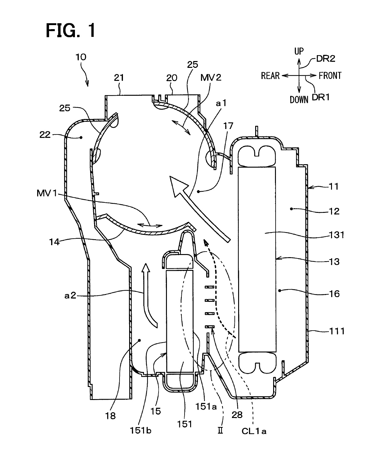
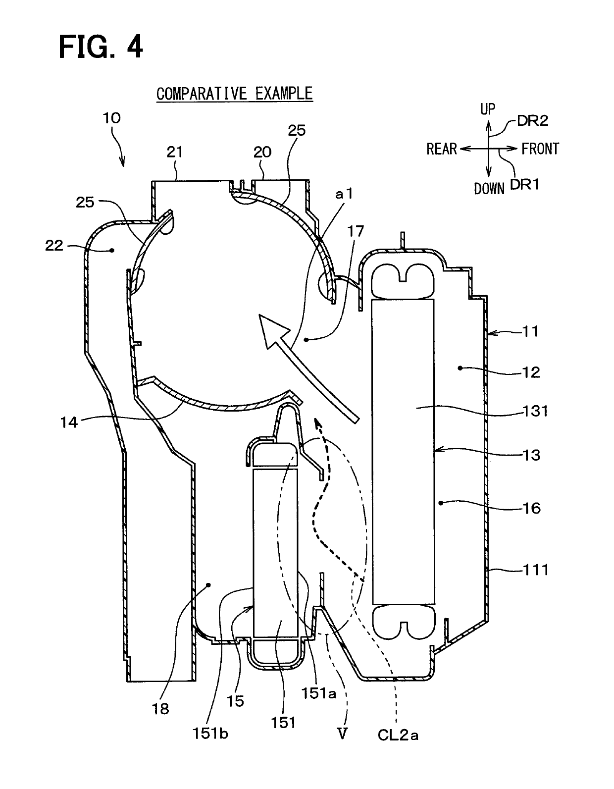
[0024]FIG. 1 is a longitudinal section illustrating a vehicle air-conditioning unit 10 (hereinafter, just referred to as air-conditioning unit 10) of an interior unit portion that is a part of a vehicle air-conditioning device having a refrigeration cycle including a compressor and a condenser provided in an engine room, for example, the vehicle air-conditioning unit 10 accommodating a heat exchanger portion. Arrows DR1, DR2 of FIG. 1 indicate directions in a vehicle mounted state where the air-conditioning unit 10 is mounted in a vehicle. A both ends arrow DR1 of FIG. 1 indicates a front-rear direction DR1 of the vehicle, and a both ends arrow DR2 indicates an up-down direction DR2 of the vehicle. A both ends arrow DR3 of FIG. 3 described below indicates a left-right direction of the vehicle, i.e. a width direction DR3 of the vehicle. The directions DR1, DR2, DR3 are perpendicular to each other.

[0025]The air-conditioning unit 10 is located at an approximately center position in the...

second embodiment

[0061]Next, a second embodiment of the present disclosure will be described. In the present embodiment, different points from the above-described first embodiment will be mainly described. Descriptions of the elements identical with or equivalent to the above-described embodiment will be omitted or simplified. This is the same as a third embodiment described below.

[0062]FIG. 6 is a longitudinal section illustrating an air-conditioning unit 10 of the present embodiment, and FIG. 6 is comparable to FIG. 1 of the first embodiment. As shown in FIG. 6, an arrangement of a heater core 15 is different from that of the first embodiment. Specifically, the heater core 15 of the first embodiment is longitudinally provide, however, the heater core 15 of the present embodiment is horizontally arranged such that an air inflow surface 151a and an air outflow surface 151b extend two-dimensionally in a horizontal direction of a vehicle.

[0063]In contrast, the hole separation portion 28 of the present...

third embodiment

[0065]Next, a third embodiment of the present disclosure will be described. In the present embodiment, different points from the above-described first embodiment will be mainly described.

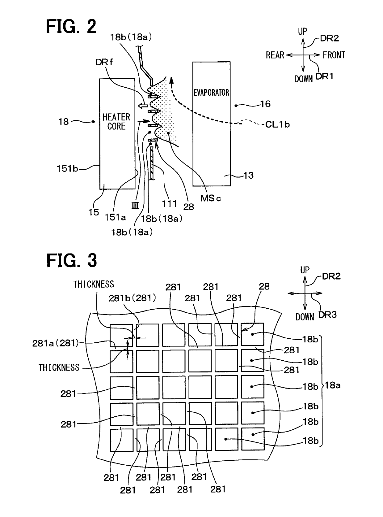
[0066]FIG. 7 is a partially enlarged diagram of the present embodiment illustrating II part of FIG. 1, and FIG. 7 is comparable to FIG. 2 of the first embodiment. As shown in FIG. 7, in the present embodiment, some of multiple plate portions 281 included in the hole separation portion 28 are provided in a different way than the first embodiment.

[0067]Specifically, some of multiple plate portions 281 that are plate portions 281c, 281d positioned on both ends in an up-down direction DR2 of a vehicle are provided along a direction such that an air passing through the opening hole 18a is blown to spread from the opening hole 18a. At least some of the separation holes 18b may have an area on a downstream end larger than that on an upstream end.

[0068]In detail, an upper side plate portion 281c positioned ...


PUM


Abstract

A vehicle air-conditioning unit includes an air-conditioning case, a heater, and an opening-closing device. The air-conditioning case includes a first air passage, a second air passage and a third air passage provided in parallel with each other. The heater is provided in the third air passage and heating the air flowing in the third air passage. The opening-closing device opens and closes the third air passage on a downstream side of the heater. The third air passage includes an opening hole that is an opening end of the third air passage on an upstream side of the heater, and the air-conditioning case includes a hole separation portion dividing the opening hole of the third air passage into a plurality of separation holes.

Description

CROSS REFERENCE TO RELATED APPLICATIONS[0001]This application is a U.S. National Phase Application under 35 U.S.C. 371 of International Application No. PCT / JP2015 / 005963 filed on Dec. 1, 2015 and published in Japanese as WO 2016 / 088361 A1 on Jun. 9, 2016. This application is based on and claims the benefit of priority from Japanese Patent Application No. 2014-246955 filed on Dec. 5, 2014. The entire disclosures of all of the above applications are incorporated herein by reference.TECHNICAL FIELD[0002]The present disclosure relates to a structure of a vehicle air-conditioning unit blowing a conditioned air into a vehicle compartment.BACKGROUND ART[0003]This kind of a vehicle air-conditioning unit includes a heating heat exchanger disposed in an air-conditioning case, and a temperature of a blown air blown from the vehicle air-conditioning unit is adjusted by adjusting a ratio of an air flowing to the heating heat exchanger to an air bypassing the heating heat exchanger. For example, ...

Claims


Application Information

Patent Timeline
Patent Type & Authority Patents(United States)
IPC IPC(8): B60H1/00F24F13/02
CPCB60H1/0005B60H1/00514F24F13/02B60H1/00564B60H2001/00635B60H2001/00092
Inventor AIZAWA, HIDEO
Owner DENSO CORP
Why Eureka
Try Eureka