Induction hob and method for operating an induction hob

a technology of induction hob and induction coil, which is applied in the direction of induction heating, electric/magnetic/electromagnetic heating, electrical apparatus, etc., can solve the problems of insufficient suppression of interference noise, flickering at the mains supply, and induction coil placed in close proximity to each other may even generate audible noise, so as to avoid interference noise generation, improve noise suppression, and wide adaptability

Active Publication Date: 2016-12-29
ELECTROLUX APPLIANCES
View PDF5 Cites 7 Cited by
  • Summary
  • Abstract
  • Description
  • Claims
  • Application Information

AI Technical Summary

Benefits of technology

The patent describes a system for reducing noise and interference in a power distribution system. The system uses different types of electronic driving means to control the output power of induction heaters. The frequency ranges of these driving means are different, which allows for flexibility in adjusting the power output without generating interference noise. The system also avoids flickering at the mains supply and provides software algorithms to keep interference noise out of the audible range. Overall, the system reduces noise and interference, improves efficiency, and provides a more stable power distribution.

Problems solved by technology

However, induction coils placed in close proximity to each other may even generate audible noise due to interference effects.
A drawback of the known induction hob is that interference noise is not suppressed sufficiently.
In addition, the alternation of output power leads to flicker at the mains supply.

Method used


Image

  • Induction hob and method for operating an induction hob
  • Induction hob and method for operating an induction hob
  • Induction hob and method for operating an induction hob

Examples


Embodiment Construction

[0026]The present invention will now be described more fully with reference to the accompanying drawings, in which example embodiments are shown. However, this invention should not be construed as limited to the embodiments set forth herein. Throughout the following description similar reference numerals have been used to denote similar elements, parts, items or features, when applicable.

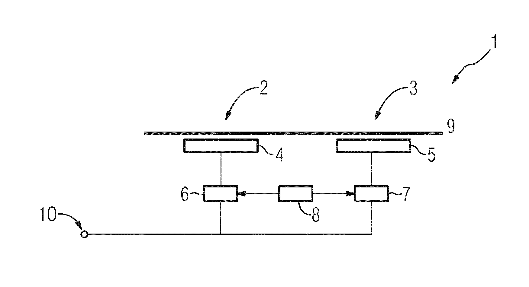
[0027]FIG. 1 shows a schematic illustration of an induction hob 1 according to the invention. The induction hob 1 comprises at least two induction heaters, namely a first induction heater 2 and a second induction heater 3 preferably provided at a common hob plate 9. Beneath the hop plate 9 two induction coils 4, 5 are arranged, wherein the first induction coil 4 is associated with the first induction heater 2 and the second induction coil 5 is associated with the second induction heater 3. The first induction coil 4 is coupled with first electronic driving means 6 of a first type, wherein said elect...


PUM


Abstract

The invention relates to an induction hob comprising at least two induction heaters (2, 3), each induction heater (2, 3) associated with at least one induction coil (4, 5), wherein a first induction heater (2) is associated with a first type of electronic driving means (6) comprising a first induction coil (4) and being adapted for driving an AC current through said first induction coil (4) of the first induction heater (2), wherein the second induction heater (3) is associated with a second type of electronic driving means (7) comprising a second induction coil (5) and being adapted for driving an AC current through said second induction coil (5) of the second induction heater (3) and wherein the electronic driving means (6, 7) are adapted to control the output power of the induction heaters (2, 3) by varying the frequency of the AC current through the respective induction coil (4, 5). Each electronic driving means (6, 7) is adapted to cause a constant electric power flow through the induction coil (4, 5) and the electronic driving means of the first and second type have different resonance frequencies such that the resonance frequency of the first type of electronic driving means (6) is at least 1.4 times higher than the resonance frequency of the second type of electronic driving means (7).

Description

[0001]The present invention relates generally to the field of induction hobs. More specifically, the present invention is related to an induction hob adapted to suppress audible interference noise.BACKGROUND OF THE INVENTION[0002]Induction hobs for preparing food are well known in prior art. Induction hobs typically comprise at least one induction heater which is associated with at least one induction coil. For heating a piece of cookware placed on the induction hob, the induction coil is coupled with electronic driving means for driving an AC current through the induction coil. Said AC current generates a time verifying magnetic field. Due to the inductive coupling between the inductor coil and the piece of cookware placed on the induction hob, the magnetic field generated by the inductor coil causes eddy currents circulating in the piece of cookware. The presence of said eddy currents generates heat within the piece of cookware due to the electrical resistance of said piece of coo...

Claims


Application Information

Patent Timeline
IPC IPC(8): H05B6/06H05B6/08
CPCH05B6/08H05B6/065
Inventor CHRISTIANSEN, SVEND ERIKJEANNETEAU, LAURENTVIROLI, ALEXZANNONI, LUCA
Owner ELECTROLUX APPLIANCES
Why Eureka
Try Eureka