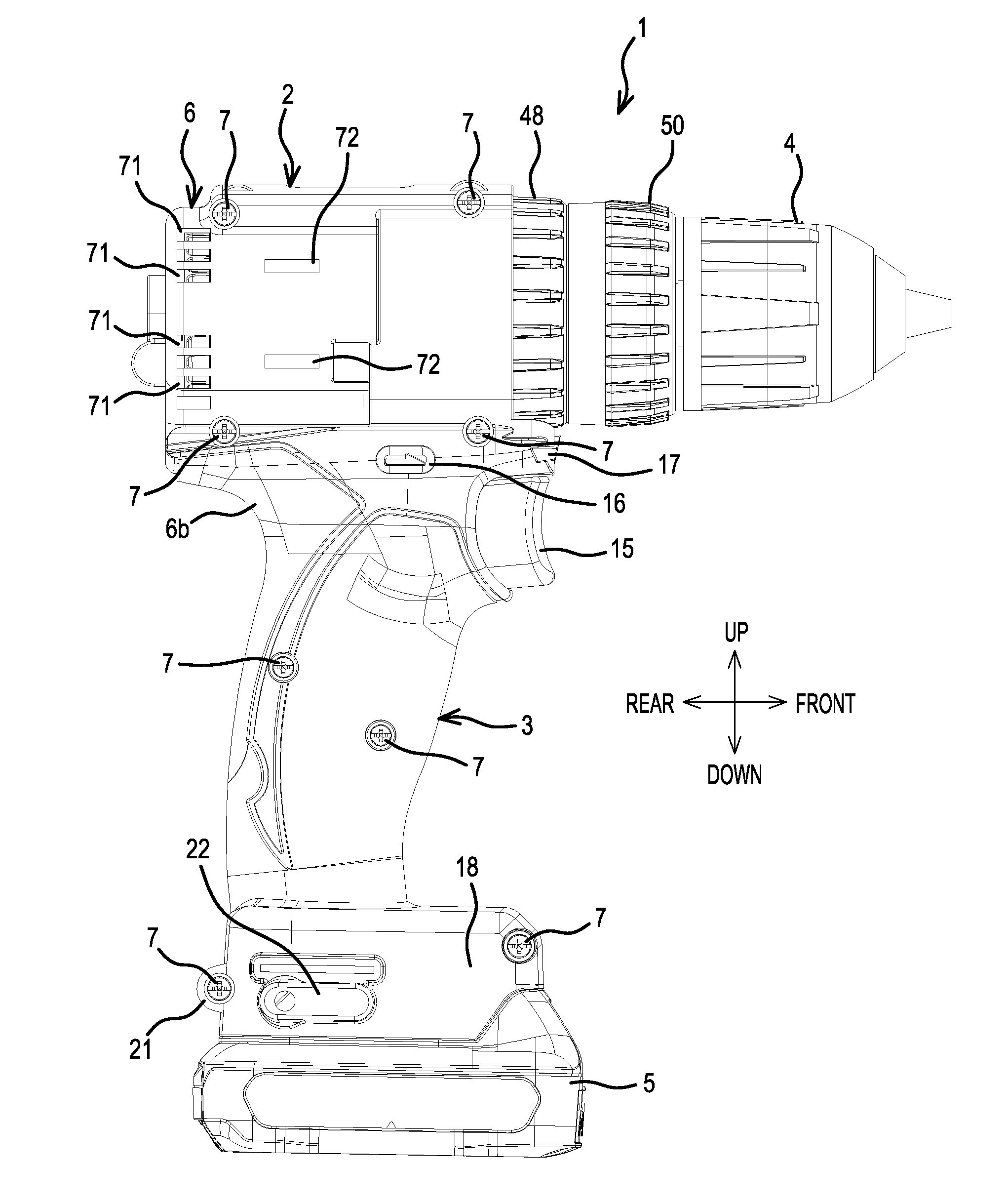
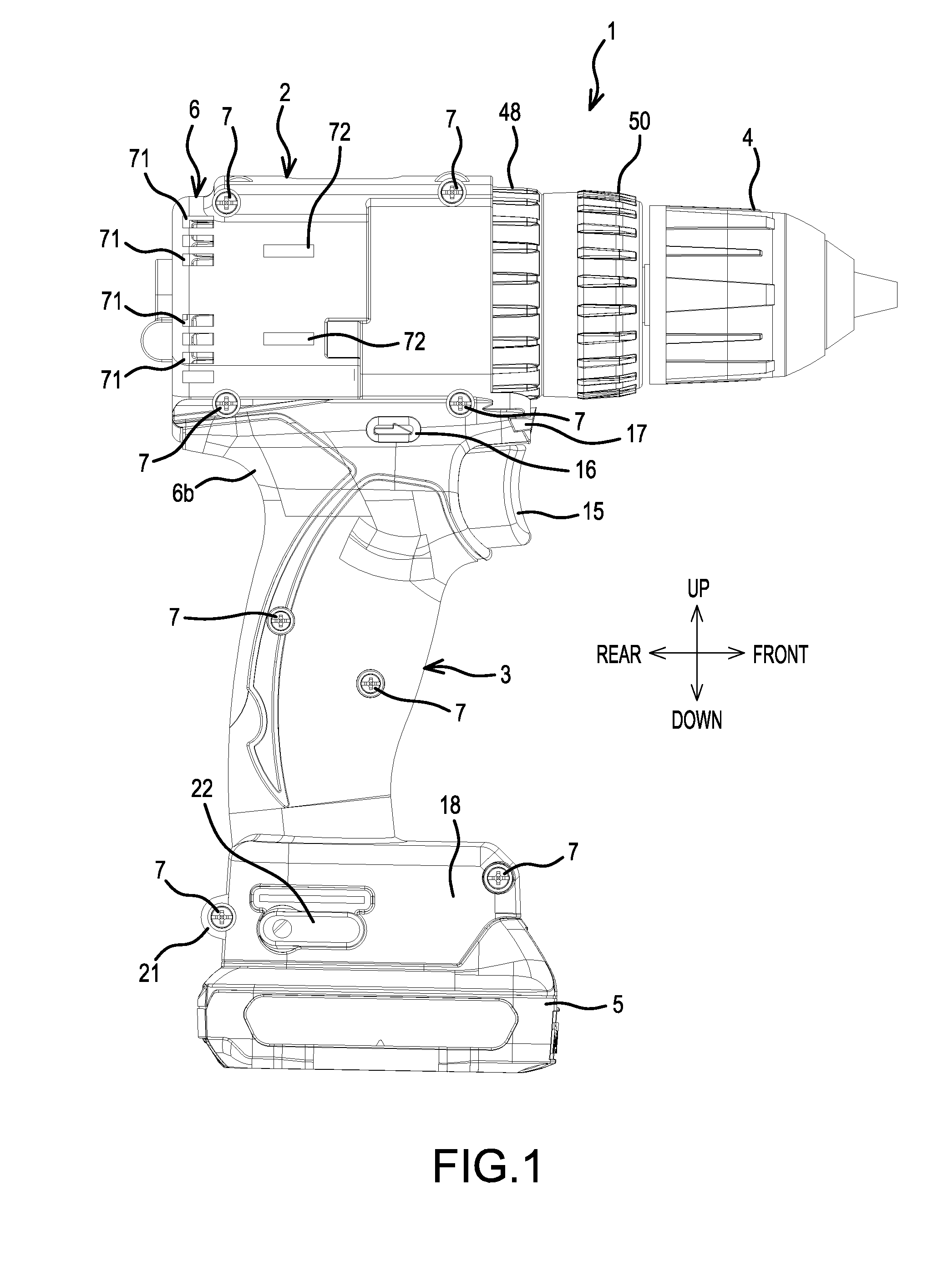
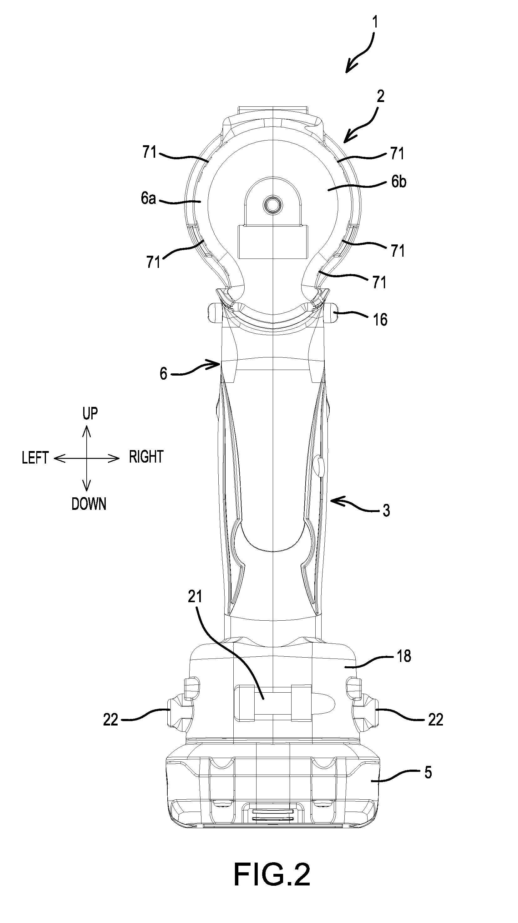
Power tool

a power tool and tool body technology, applied in the field of power tools, can solve the problems of unnecessarily labor-intensive and costly repair, replacement and/or inspection, and achieve the effect of inspected and/or repaired more quickly and more cost-effectively

Active Publication Date: 2016-12-29
MAKITA CORP
View PDF11 Cites 24 Cited by
  • Summary
  • Abstract
  • Description
  • Claims
  • Application Information

AI Technical Summary

Benefits of technology

The patent is about a power tool with a brushless motor that is easier and more efficient to repair and inspect. The tool can be examined and fixed more quickly and inexpensively than older tools with the same motor.

Problems solved by technology

This makes repair, replacement and / or inspection unnecessarily labor-intensive and costly.

Method used


Image

  • Power tool
  • Power tool
  • Power tool

Examples


embodiment 1

[0087]2. A power tool , wherein the first power-supply line is provided with a first connection terminal, the second power-supply line is provided with a second connection terminal and the first connection terminal is releasably connected to the second connection terminal.

[0088]3. A power tool according to embodiment 1 or 2, wherein second the power supply line is connected to the coil such that a sensor circuit board connected to the stator is removable from the stator without moving the power supply line.

[0089]4. A power tool, comprising a stator comprising a coil; a rotor configured to rotate with respect to the stator; a tool-accessory retaining part configured to be driven by the rotor; a fusing terminal fixed to the stator and connected to the coil; and a power-supply line that comprises stranded wires and is configured to supply electric current to the coil, wherein the power-supply line is connected to the fusing terminal and includes a stranded-wire-fray preventing means fo...

embodiment 4

[0090]5. A power tool according to embodiment 4, wherein the power-supply line comprises a covered part that covers the stranded wires; and wherein the stranded-wire-fray preventing means comprises a covering-remaining part, and the power-supply line includes an exposed part at which the stranded wires are exposed, wherein the exposed part is located between the covered part and the covering-remaining part.


PUM


Abstract

A power tool includes a stator having a coil, a sensor circuit board attached to the stator and on which a magnetic sensor is provided, the sensor circuit board having a first side facing the stator and a second side opposite the first side, a rotor configured to rotate with respect to the stator, a tool-accessory retaining part configured to be driven by the rotor and a power-supply line configured to supply electrical power to the coil. The power-supply line is connected to the coil without traversing the second side of the sensor circuit board.

Description

CROSS-REFERENCE[0001]The present application claims priority to Japanese patent application serial number 2015-127986 filed Jun. 25, 2015, the contents of which are incorporated fully herein by reference.TECHNICAL FIELD[0002]The present disclosure relates to a power tool such as a driver-drill.BACKGROUND ART[0003]A driver-drill that utilizes a brushless motor is known. The brushless motor of the driver-drill comprises a sensor circuit board, on which rotation-detection devices are mounted. The rotation detection devices are configured to detect the positions of permanent magnets provided on a rotor and to output rotation-detection signals. The brushless motor also includes a stator having a stator core on which multiple coils are sequentially wound in a delta configuration.SUMMARY OF THE INVENTION[0004]In the above-described driver-drill, signal lines are fastened to the sensor circuit board, and power-supply lines are welded in place; consequently, unless all the signal lines and p...

Claims


Application Information

Patent Timeline
Patent Type & Authority Applications(United States)
IPC IPC(8): H02K7/14H02K9/06H02K3/12H02K11/00H02K11/215H02K1/27
CPCH02K7/145H02K11/215H02K9/06H02K3/12H02K11/0094H02K1/2706B25F5/00H02J7/00H02K29/00H02K3/522H02K29/08
Inventor NIWA, AKIRA
Owner MAKITA CORP
Why Eureka
Try Eureka