
Optical reflection film

a reflection film and optical technology, applied in the field of optical reflection films, can solve the problems of uneven thickness of film (layer thickness) of respective layers of reflection units, iridescent light interference, irregular iridescence, etc., and achieve excellent optical reflection performance and light transmittance, suppress iridescent irregularities, and reduce the effect of iridescen

Inactive Publication Date: 2016-12-29
KONICA MINOLTA INC
View PDF5 Cites 3 Cited by
  • Summary
  • Abstract
  • Description
  • Claims
  • Application Information

AI Technical Summary

Benefits of technology

The patent text describes a new way to make an optical reflection film that avoids the problem of unevenness and thickness among layers. By adding a layer with a high birefringence, the film produces noticeable interference patterns that are dispersed over a wider range of wavelengths. This leads to reduced "iridescent" defects and improved optical performance. The invention also addresses the issue of thickness unevenness by adding a layer with a lower birefringence to further reduce interference patterns. Overall, the patent describes a way to make a more reliable and effective optical reflection film.

Problems solved by technology

However, optical anisotropy occurs in the lamination structure due to unevenness of birefringence or film thickness (layer thickness) of respective layers constituting the reflection unit of such an optical reflection film, and thus iridescent light interference color which is expressed on the surface of the optical reflection film by light interference (hereinafter, referred to as iridescent irregularities) may occur.
It is considered that the unevenness of film thickness (layer thickness) of respective layers constituting the reflection unit is caused by unevenness of molecular distribution, smoothness of the surface, distortion or deformation of the layer generated in the producing step, or the like.
However, according to the method of Patent Literature 1, iridescent irregularities are reduced, but since the haze value is as high as 40 to 60, a problem arises in which light transmittance is low.
Further, in the case of an optical reflection film which reflects light with a specific wavelength by a reflection unit obtained by alternately laminating a high-refractive-index layer and a low-refractive-index layer, if the refractive index and film thickness (layer thickness) of each layer are adjusted, optical reflection performance is adversely affected.
Therefore, according to the method of Patent Literature 2 in which iridescent irregularities are suppressed by controlling the refractive index and the film thickness (layer thickness), optical reflection performance is deteriorated.

Method used


Image

  • Optical reflection film
  • Optical reflection film
  • Optical reflection film

Examples


example 1-1

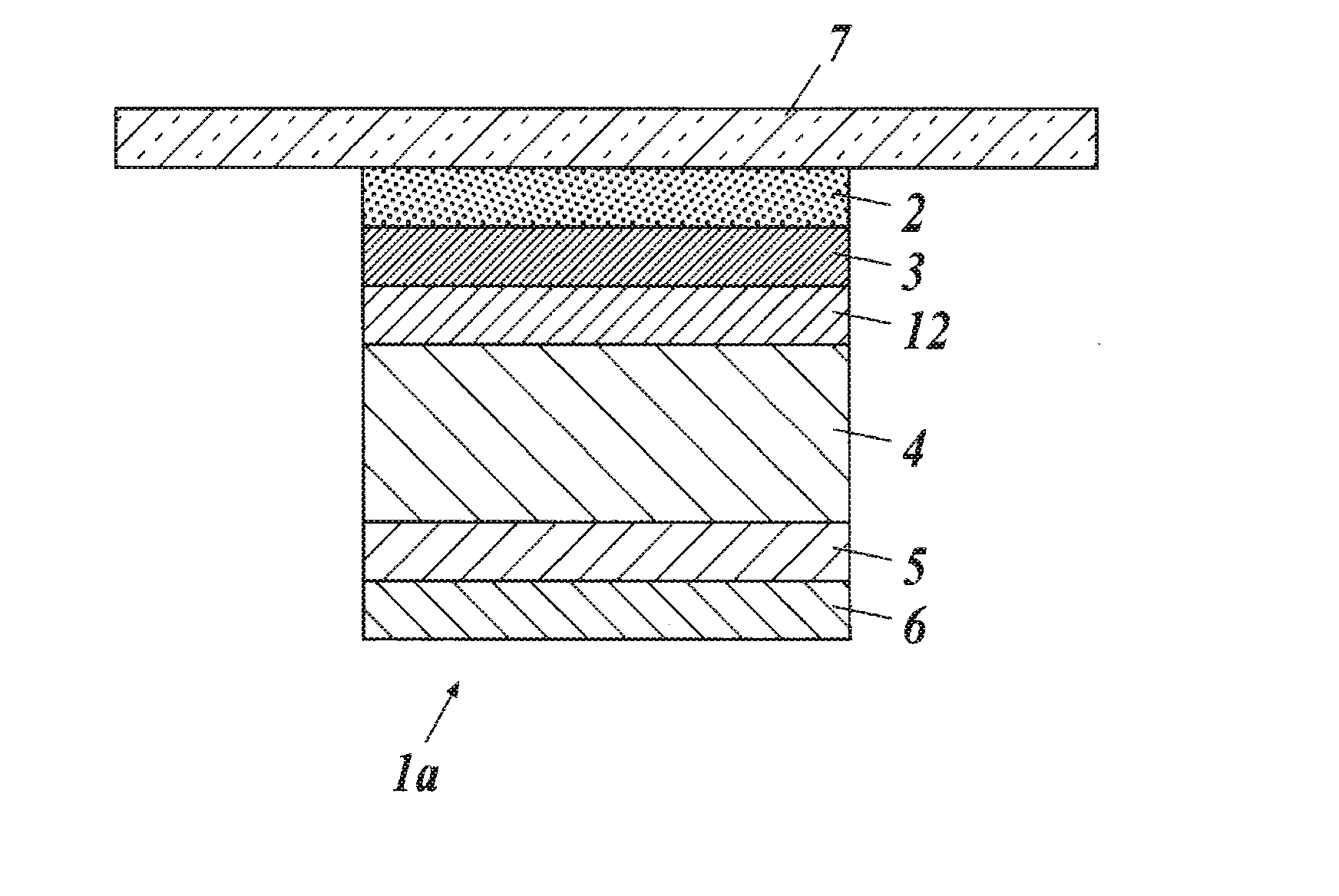
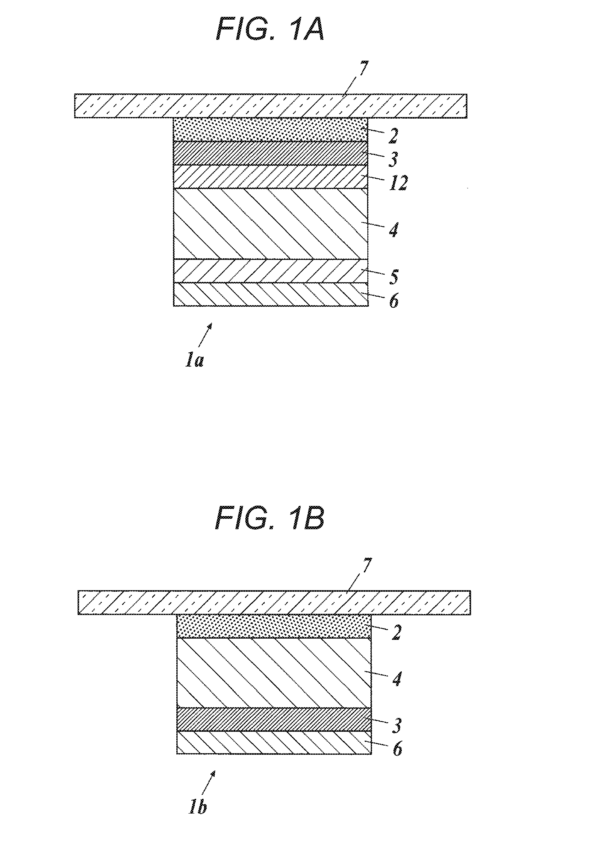
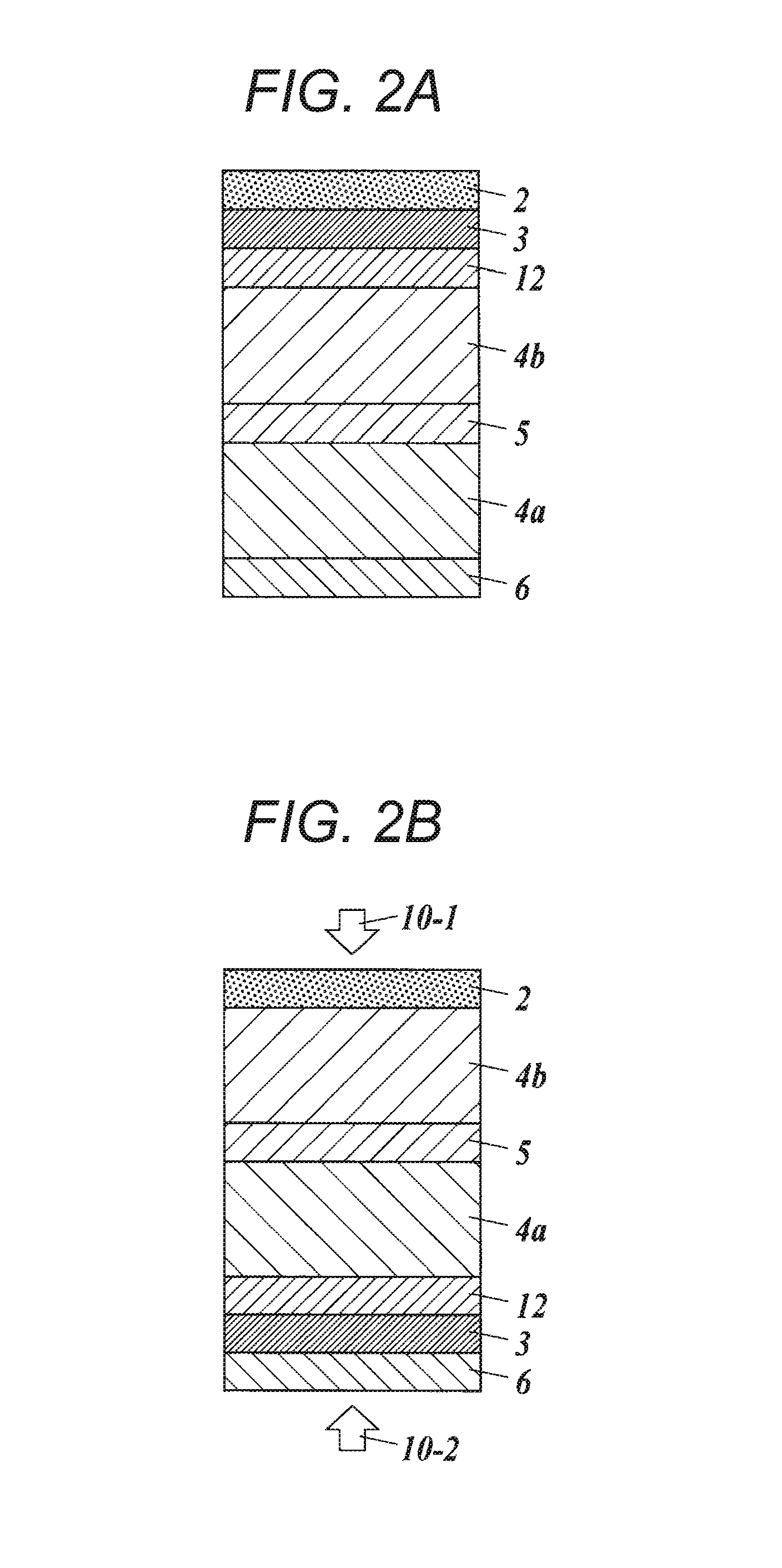
[0159]The layer configuration of an optical reflection film in the Example 1-1 was illustrated in FIG. 2A.

[0160]Simultaneous multilayer coating of 22 layers in total was carried out using a slide hopper coating apparatus such that while the coating liquid for a low-refractive-index layer and the coating liquid for a high-refractive-index layer obtained above were kept warm at 45° C., low-refractive-index layers and high-refractive-index layers were formed on the base material 5 of a polyethylene terephthalate film (A4300 manufactured by TOYOBO CO., LTD.: double-sided easy adhesive layer, 200 m in length×210 mm in width) having a thickness of 50 μm and heated to 45° C. with both outermost layers being low-refractive-index layers, while other layers being alternately laminated, and the film thickness upon drying was 150 nm for each of the low-refractive-index layers and 130 nm for each of the high-refractive-index layers. Incidentally, regarding the confirmation of a mixed region betw...

example 1-2

[0166]An optical reflection film a-2 was produced in the same conditions as in Example 1-1, except that the birefringence layer was changed to a PET film B.

example 1-3

[0167]An optical reflection film a-3 was produced in the same conditions as in Example 1-1, except that the birefringence layer was changed to a PET film C.


PUM


Abstract

An object of the present invention is to provide an optical reflection film which is suppressed in iridescent irregularities caused by unevenness of birefringence or film thickness among layers of a reflection unit and has excellent optical reflection performance and light transmittance.The optical reflection film of the present invention, having a plurality of function layers includes at least: a reflection unit that is obtained by alternately laminating a high-refractive-index layer and a low-refractive-index layer and reflects light; and a birefringence layer that has an in-plane retardation of 3000 nm or more.

Description

TECHNICAL FIELD[0001]The present invention relates to an optical reflection film.BACKGROUND ART[0002]In general, a reflection unit that selectively reflects light with a specific wavelength by adjusting the respective optical film thicknesses of high-refractive-index layers and low-refractive-index layers and alternately laminating the layers, is utilized as an optical reflection film that selectively reflects near-infrared rays, ultraviolet rays, and the like. Such an optical reflection film is used as a heat-ray shielding film to be pasted, for example, on buildings or vehicles.[0003]However, optical anisotropy occurs in the lamination structure due to unevenness of birefringence or film thickness (layer thickness) of respective layers constituting the reflection unit of such an optical reflection film, and thus iridescent light interference color which is expressed on the surface of the optical reflection film by light interference (hereinafter, referred to as iridescent irregula...

Claims


Application Information

Patent Timeline
Patent Type & Authority Applications(United States)
IPC IPC(8): G02B5/30G02B1/14B60J3/00G02B5/08
CPCG02B5/3083B60J3/007G02B1/14G02B5/0841G02B5/26G02B5/0833
Inventor HONDA, MAKOTO
Owner KONICA MINOLTA INC
Learn More