Connector

Active Publication Date: 2016-12-22
FUJITSU COMPONENENT LTD +1
View PDF3 Cites 0 Cited by
  • Summary
  • Abstract
  • Description
  • Claims
  • Application Information

AI Technical Summary

Benefits of technology

The invention is a connector that can safely receive power from high-voltage or direct-current power supplies and use it to power devices. This means that the invention can handle higher voltages and provide greater safety than existing connectors.

Problems solved by technology

On the other hand, when electric power supplied to an electric apparatus has a high voltage, the electric power may affect the human body and operations of electronic components.

Method used


Image

  • Connector
  • Connector
  • Connector

Examples


Embodiment Construction

[0031]Embodiments of the present invention are described below. The same reference number is assigned to the same component, and repeated descriptions of the same component are omitted.

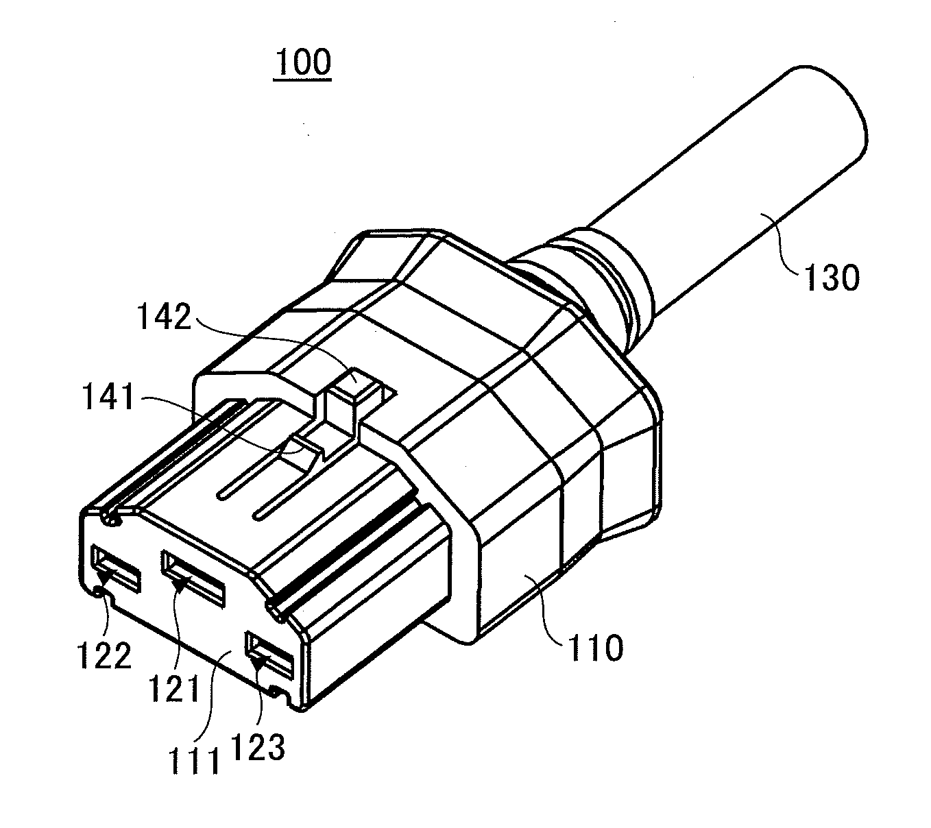
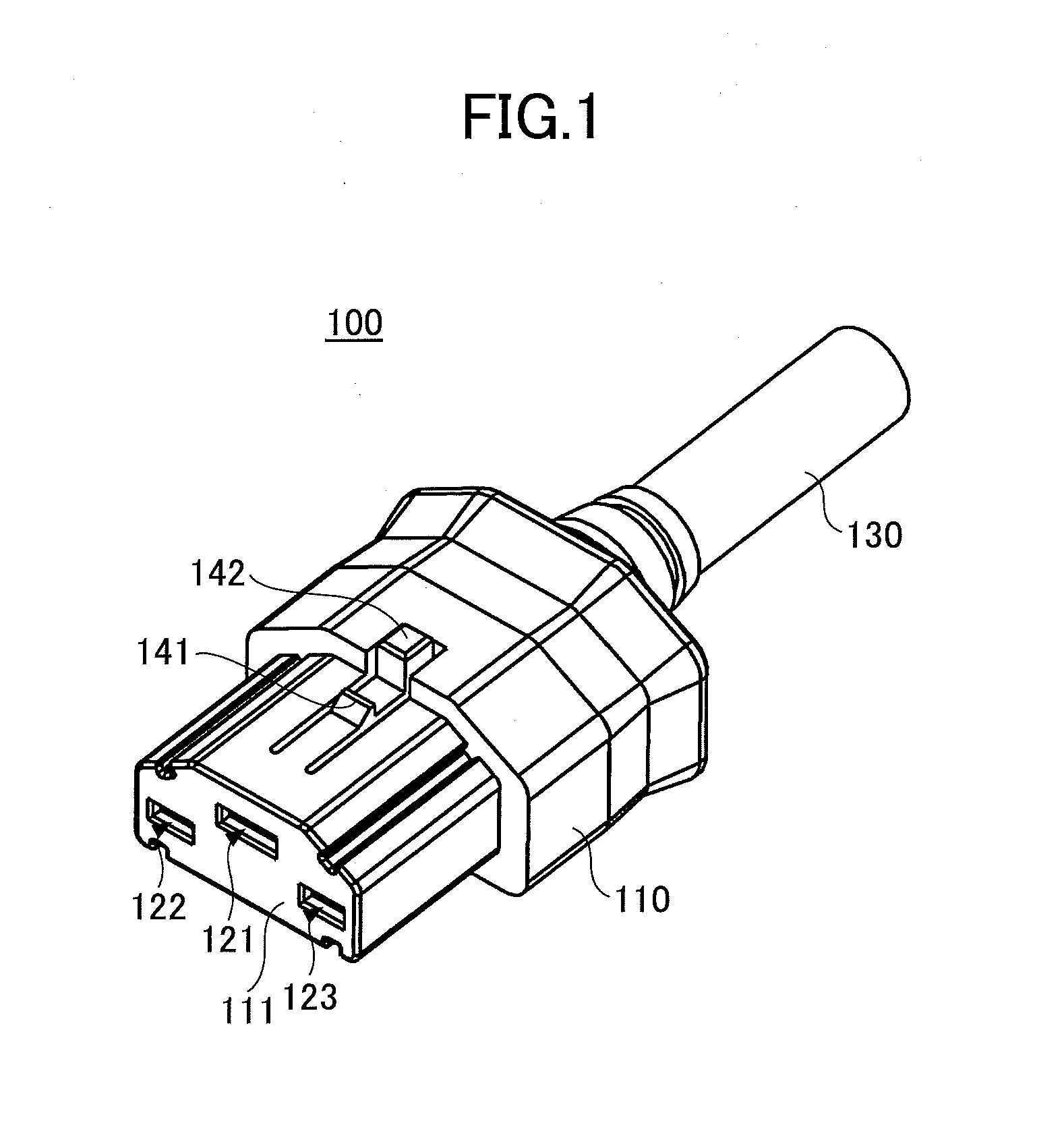
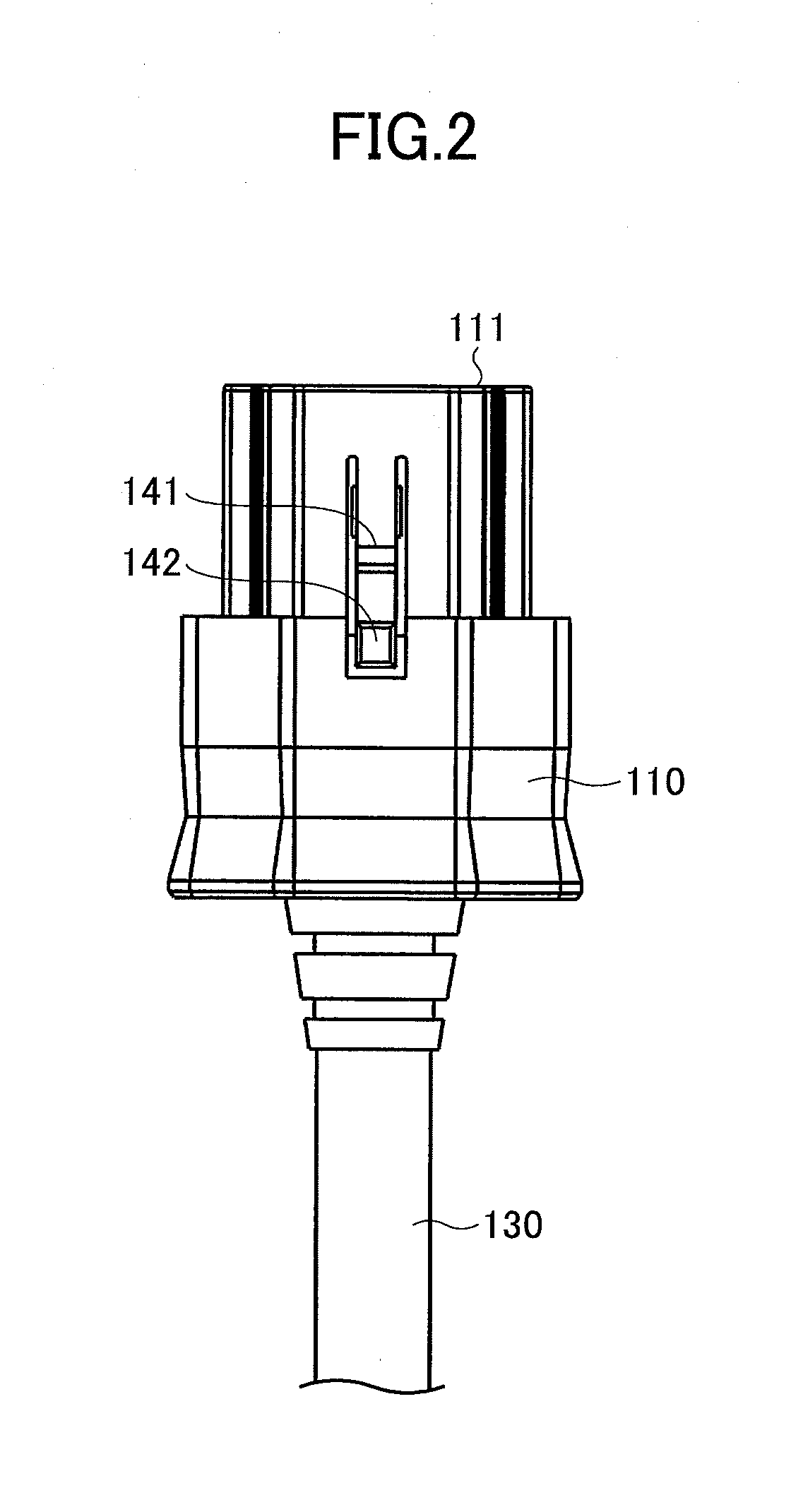
[0032]A configuration of a connector according to an embodiment is described below. A connector of the present embodiment is to be connected to another connector, which is a jack connector illustrated by FIGS. 1 through 4, and corresponds to a plug connector whose configuration is illustrated by FIGS. 5 through 9. In the present embodiment, the jack connector illustrated by FIGS. 1 through 4 and the connector corresponding to the plug connector illustrated by FIGS. 5 through 9 may be collectively referred to as a “connector”. FIG. 10 is a cut-away view and FIG. 11 is a cut-away perspective view of a jack connector and a plug connector.

[0033]First, a jack connector 100 is described with reference to FIGS. 1 through 4. FIG. 1 is a perspective view, FIG. 2 is a top view, FIG. 3 is a side view, and FIG. 4...


PUM


Abstract

A connector that is to be connected to another connector and includes a connection terminal, a fixed contact, a movable contact provided at an end of a movable plate, a card comprised of an insulator and configured to move the movable plate, and a button configured to move the card. The connector is configured such that while another connection terminal of the another connector is in contact with the connection terminal of the connector, the button is moved by the another connector, and the movable plate is moved by the card to cause the movable contact to contact the fixed contact.

Description

TECHNICAL FIELD[0001]The present invention relates to a connector.BACKGROUND ART[0002]Generally, an electric apparatus is driven by electric power supplied from a power supply. An electric apparatus typically receives electric power via a connector from a power supply. Patent Documents 1 and 2 disclose a connector unit including a protruding male connector and a hollow female connector that are fitted together to be electrically connected.[0003]In recent years, as a measure to cope with global warming, it is being considered to use, even for power transmission in local areas, a direct-current high-voltage power that suffers less power loss during voltage conversion and power transmission and does not necessitate increasing the diameter of a cable. Supplying electric power in this manner is particularly preferable for an information apparatus such as a server that consumes a large amount of electric power.[0004]On the other hand, when electric power supplied to an electric apparatus ...

Claims


Application Information

Patent Timeline
IPC IPC(8): H01R13/703H01R24/70
CPCH01R13/7038H01R2103/00H01R24/70
Inventor KIRYU, KOICHISHIMIZU, MANABUNORITAKE, MASATOSHIHIROSE, KEIICHI
Owner FUJITSU COMPONENENT LTD
Why Eureka
Try Eureka