
Helicopter blade folding apparatus

a helicopter blade and folding technology, applied in the field of helicopter blade folding apparatus, can solve the problems of significant space claim issues, complicated rebalancing procedures of helicopters, complicated devices powered by hydraulic, pneumatic and/or electrical automatic folding devices, etc., to achieve less difficult and more controlled folding of main rotor blades, and improve the control of balanced control of blades. , the effect of reducing stress and loads

Active Publication Date: 2016-12-22
HII MISSION TECH CORP
View PDF31 Cites 3 Cited by
  • Summary
  • Abstract
  • Description
  • Claims
  • Application Information

AI Technical Summary

Benefits of technology

This patent describes an improved method for supporting and controlling the blades of a helicopter's main rotor. The method allows for better balanced control of the blades, making the folding and unfolding process simpler and more efficient. The invention also includes a mechanism for safely and easily removing the blade pins and other items required for repetitive folding and unfolding procedures. The use of this invention may reduce the need for external equipment and facilitate quick blade fold and unfold procedures with reduced personnel requirement and workload. Additionally, the invention includes adjustable blade support beams that can be quickly installed on the overhead lifting system support structure and blade clamps that can be attached to each individual main rotor blade for maximum control and easy removal.

Problems solved by technology

This feature, however, causes significant space claim issues when the helicopter is not in use or needs to be transported long distances in transport aircraft or on the crowded deck of sea going vessels, which is often the case.
Removing the blades from a host helicopter requires that the helicopter go through lengthy and complex rebalancing procedures before flying once again.
These devices, powered by hydraulic, pneumatic and / or electrical automatic folding devices are quite complex and their extensive weight and complexity prevent them from being incorporated on a wide scale on lightweight civilian and military helicopters.
Because the helicopter blades are not supported or controlled at or near the center of gravity for this operation, and only at the far end through the use of a “pole” attached to the outboard end of the blade and manually manipulated by two or more personnel, achieving balance enough to remove the forces present at the blade pins is very difficult and time consuming.
It is a common occurrence during a main rotor blade fold or main rotor blade unfold operation of the Apache Helicopter, for example, that as many as eleven people are required for the fold and unfold operations, and the time and effort required to manipulate the outward end of each main rotor blade correctly to achieve what is commonly known as the “sweet spot,” and at that moment relieving stress at the rotor blade pins sufficiently to remove the flight blade pin(s) is quite high and unacceptable.

Method used


Image

  • Helicopter blade folding apparatus
  • Helicopter blade folding apparatus
  • Helicopter blade folding apparatus

Examples


Embodiment Construction

[0041]Embodiments of the present invention are not limited to the particular methodology, uses, and applications described herein, as these may vary. It is also to be understood that the terminology used herein is used for the purpose of describing particular embodiments only, and is not intended to limit the scope of all embodiments of the present invention. It must be noted that as used herein and in the appended claims, the singular forms “a,”“an,” and “the” include the plural reference unless the context clearly dictates otherwise. Thus, for example, a reference to “an element” is a reference to one or more elements, and includes equivalents thereof known to those skilled in the art. Similarly, for another example, a reference to “a step” or “a means” is a reference to one or more steps or means and may include sub-steps or subservient means. All conjunctions used are to be understood in the most inclusive sense possible. Thus, the word “or” should be understood as having the de...


PUM


Abstract

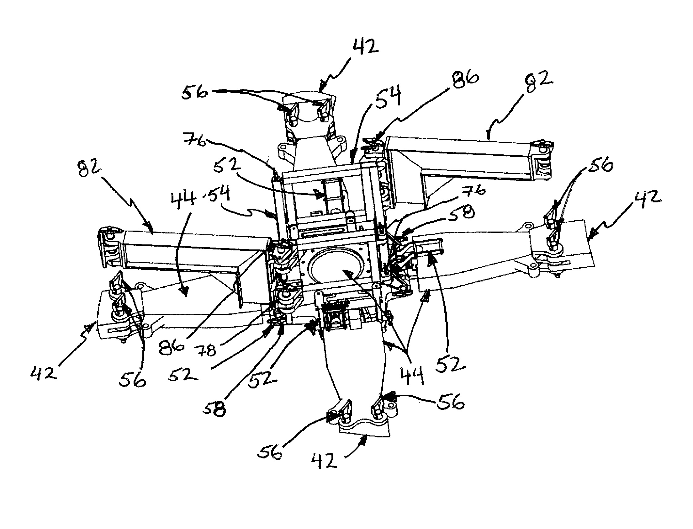
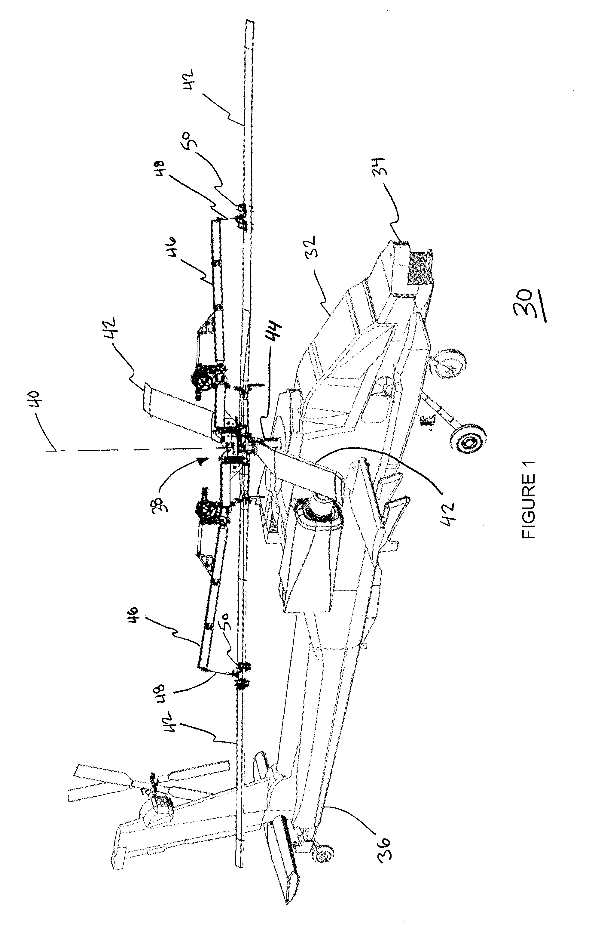
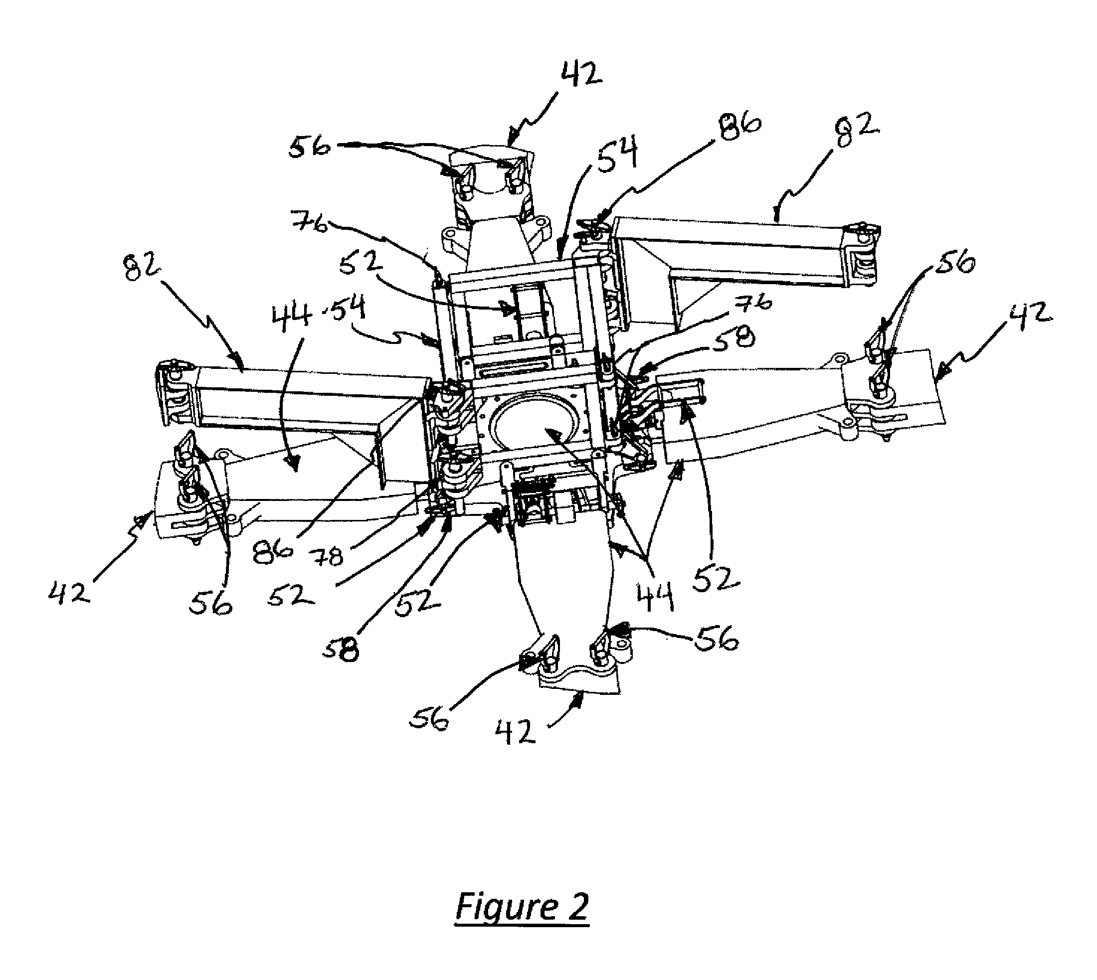
The present invention relates to a blade folding apparatus that may incorporate an overhead blade lifting system that reduces binding loads on blade pins induced by blade weight and pitch, and a folding mechanism that removes the necessity of personnel with external guide-poles to rotate main rotor blades. The apparatus may include flap locks, an overhead lifting system support structure attached to the flap locks, and two blade support beams to create and support a lifting point near each blade's longitudinal and lateral center of gravity. The blade support beams may be fitted with an articulation mechanism that lifts and / or lowers the overhead lifting structure. The apparatus facilitates rapid folding of the main rotor blades, and, when used with blade clamping mechanisms, is capable of aiding in the removal and / or the re-installation of the main rotor blades without external lifting mechanisms.

Description

CROSS-REFERENCE TO RELATED APPLICATION[0001]This application claims the benefit of the filing date under 35 USC 119(e) of U.S. Provisional Application entitled “Helicopter Blade Folding Apparatus,” Ser. No. 62 / 163,662 filed May 19, 2015, the entire contents of which are incorporated herein by reference.STATEMENT REGARDING GOVERNMENT SUPPORT[0002]Some of the information disclosed herein may be determined to relate to inventions made with Government support and to the extent any such information ultimately becomes the subject of allowed claims, the Government may have certain rights in those claimed inventions.BACKGROUND OF THE INVENTION[0003]1. Field of the Invention[0004]This invention pertains to the folding and unfolding of helicopter blades.[0005]2. Description of the Prior Art[0006]It is an accepted and necessary design feature of helicopters to have a large diameter swept area of the main rotor blades. This feature, however, causes significant space claim issues when the helico...

Claims


Application Information

Patent Timeline
Patent Type & Authority Applications(United States)
IPC IPC(8): B64C27/50
CPCB64C27/50
Inventor PETERSON, ERICSCHWEITZER, JEREMIAHANDERSON, ZACHARY
Owner HII MISSION TECH CORP
Learn More