
Sensor wire count reduction system

Active Publication Date: 2016-12-15
THE BF GOODRICH CO
View PDF6 Cites 5 Cited by
  • Summary
  • Abstract
  • Description
  • Claims
  • Application Information

AI Technical Summary

Benefits of technology

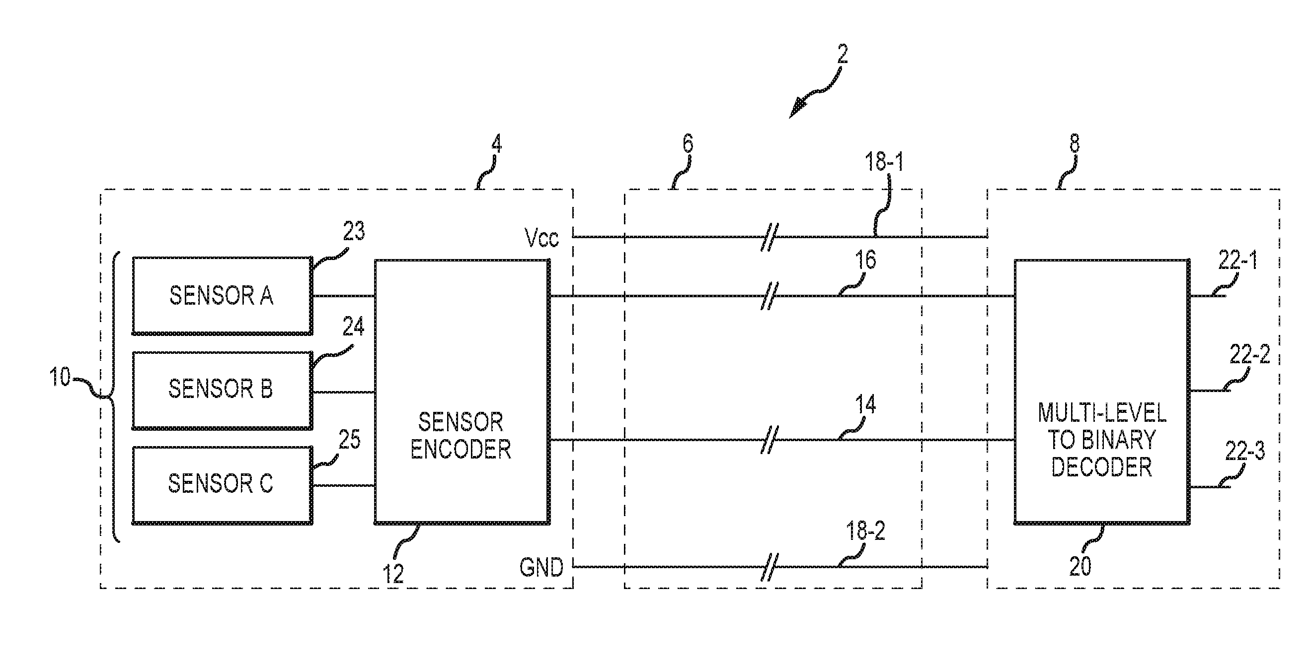
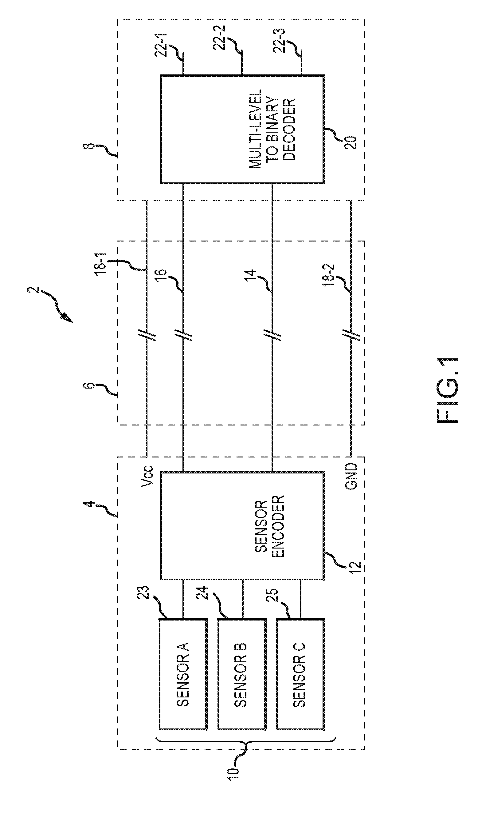
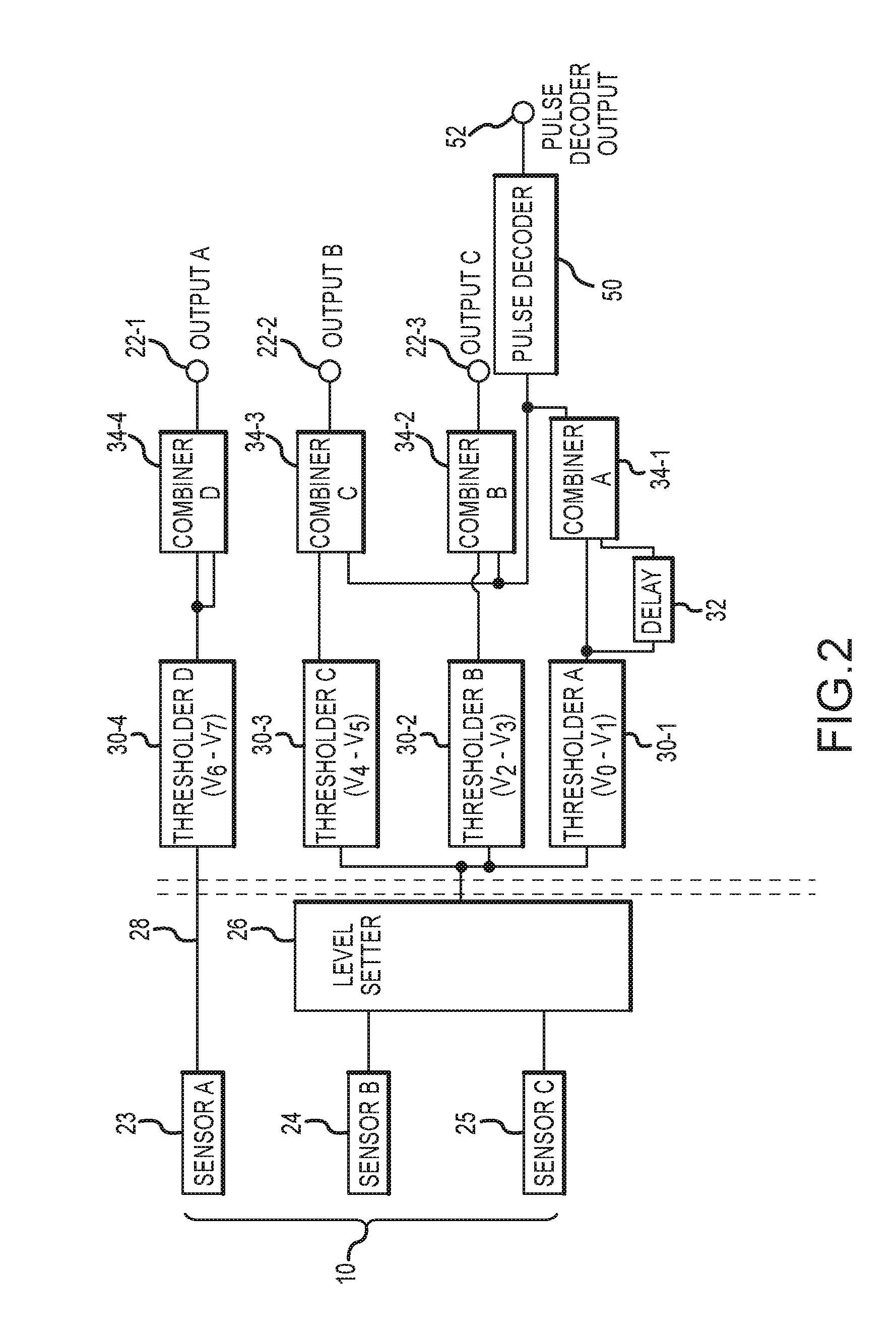
The present invention provides a method for reducing the number of sensor wires in a sensor array. The method involves receiving a first binary indication of sensor state for a first sensor, a second binary indication of sensor state for a second sensor, and a third binary indication of sensor state for a third sensor. A voltage is set based on the first and second indications, and a range of the voltage is determined. The method also involves combining the first and third indications, providing two outputs that indicate the state of the first and second sensors, respectively. The method can be implemented using Hall Effect sensors. The technical effect of the invention is to reduce the number of sensor wires needed in a sensor array.

Problems solved by technology

Thus, each sensor often requires its own wire.

Method used


Image

  • Sensor wire count reduction system
  • Sensor wire count reduction system
  • Sensor wire count reduction system

Examples


Embodiment Construction

[0012]The following description is of various exemplary embodiments only, and is not intended to limit the scope, applicability or configuration of the present disclosure in any way. Rather, the following description is intended to provide a convenient illustration for implementing various embodiments including the best mode. As will become apparent, various changes may be made in the function and arrangement of the elements described in these embodiments without departing from the scope of the appended claims.

[0013]For the sake of brevity, conventional techniques for manufacturing and construction may not be described in detail herein. Furthermore, the connecting lines shown in various figures contained herein are intended to represent exemplary functional relationships and / or physical couplings between various elements. It should be noted that many alternative or additional functional relationships or physical connections may be present in a practical method of construction.

[0014]...


PUM


Abstract

A sensor wire count reduction system having various features is disclosed. Signals from multiple sensors may be combined together to reduce the number of wires implemented to convey the signals to a remote location. Multiple binary sensor outputs may be represented on a single wire as a multi-level signal, and may be decoded at a remote location.

Description

CROSS REFERENCE TO RELATED APPLICATIONS[0001]This application is a divisional application of, and claims priority to, U.S. application Ser. No. 14 / 291,391, filed May 30, 2014 and titled “SENSOR WIRE COUNT REDUCTION SYSTEM,” which is hereby incorporated by reference in its entirety.FIELD[0002]The present invention relates to the field of sensors. More particularly, the present invention relates to a system for communicating data from motor position sensors.BACKGROUND[0003]Aircraft have utilized various motor position sensor systems to provide commutation for different motors, for example, brake actuator motors. Often various control components are connected to the brake actuator motors and the motor position sensor systems by cables. Often, a sensor is connected to other systems by a dedicated mechanism, for communicating electronic information such as a sensor signal. Often this dedicated mechanism is a dedicated wire within a cable. Thus, each sensor often requires its own wire.SUM...

Claims


Application Information

Patent Timeline
Patent Type & Authority Applications(United States)
IPC IPC(8): G01D5/14
CPCG01D5/142G08C15/02H03M5/20H04L25/4917H04Q9/00H04Q2209/30
Inventor KLODE, HARALDPANT, ALBERT KEITH
Owner THE BF GOODRICH CO
Learn More