Framing scheme for continuous optical transmission systems

a transmission system and frame scheme technology, applied in the direction of transmission/receiver shaping networks, fibre transmission, transmission, etc., can solve the problems of inability to predict the shape of the channel, the characteristics of the channel are rarely known in advance, and the implementation of filters is difficult. to achieve the effect of increasing the robustness against the dependence of pattern effects

Active Publication Date: 2016-12-08
MULTIPHY
View PDF8 Cites 6 Cited by
  • Summary
  • Abstract
  • Description
  • Claims
  • Application Information

AI Technical Summary

Benefits of technology

The patent text explains increasing resistance against changes in pattern by using pilot sequences with different characteristics.

Problems solved by technology

Optical and other high-speed communication channels suffer from dispersion which changes the shape of pulses which encode symbols being transmitted.
However, the characteristics of the channel are rarely known in advance, and are time-varying.
In addition, there is always imprecision that arises in implementation of the filters.
Therefore, there is always some distortion such that ISI will limit the data rate of the system.
Therefore, blind equalization (in which there is no available prior knowledge about the channel properties) is not sufficient for wireless systems.
On the other hand, wired communication systems do not use training sequences to estimate distortions in the communication channel, and equalization is mostly based on blind equalization, since changes in the CSI are very slow and there is sufficient time to perform good tracking (of changes).
However, the channel conditions in optical communication links are relatively very difficult to equalize (due to severe distortions) and therefore, the accuracy and reliability of channel tracking will not be sufficient for effective and robust equalization.

Method used


Image

  • Framing scheme for continuous optical transmission systems
  • Framing scheme for continuous optical transmission systems
  • Framing scheme for continuous optical transmission systems

Examples


Embodiment Construction

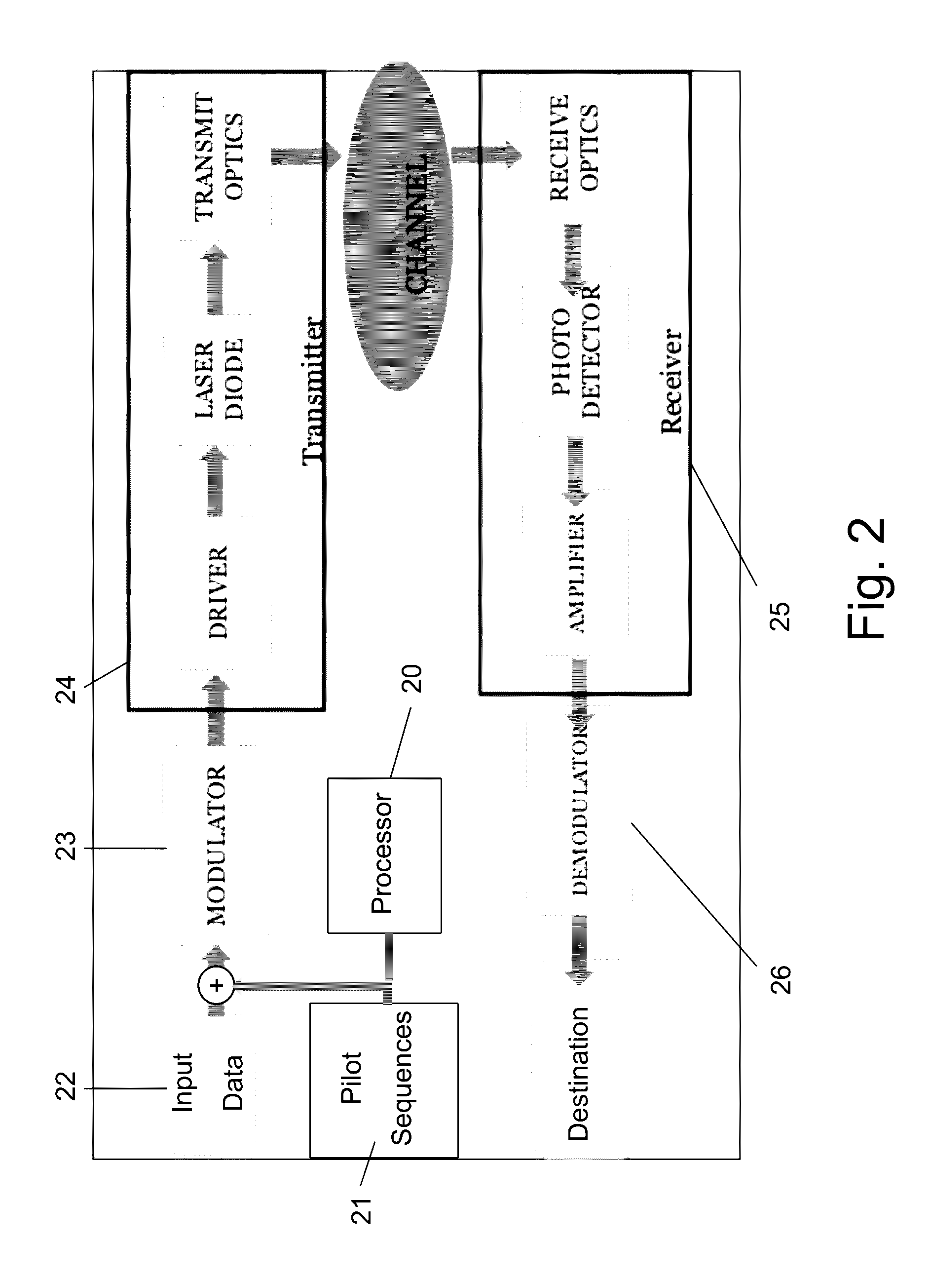
[0024]The present invention proposes a system and method for accurate and robust channel tracking technique, for achieving effective and robust equalization of optical communication channels.

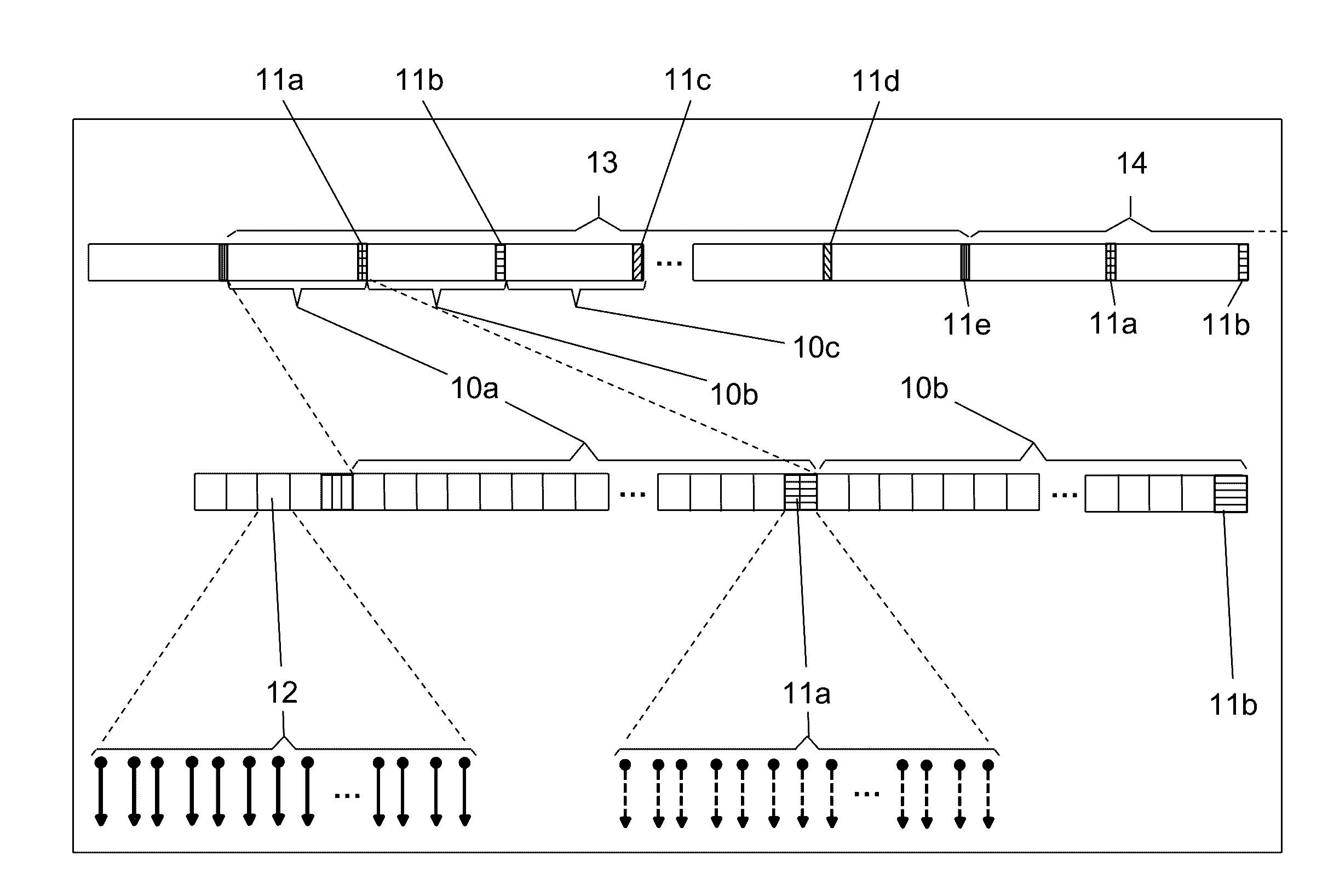
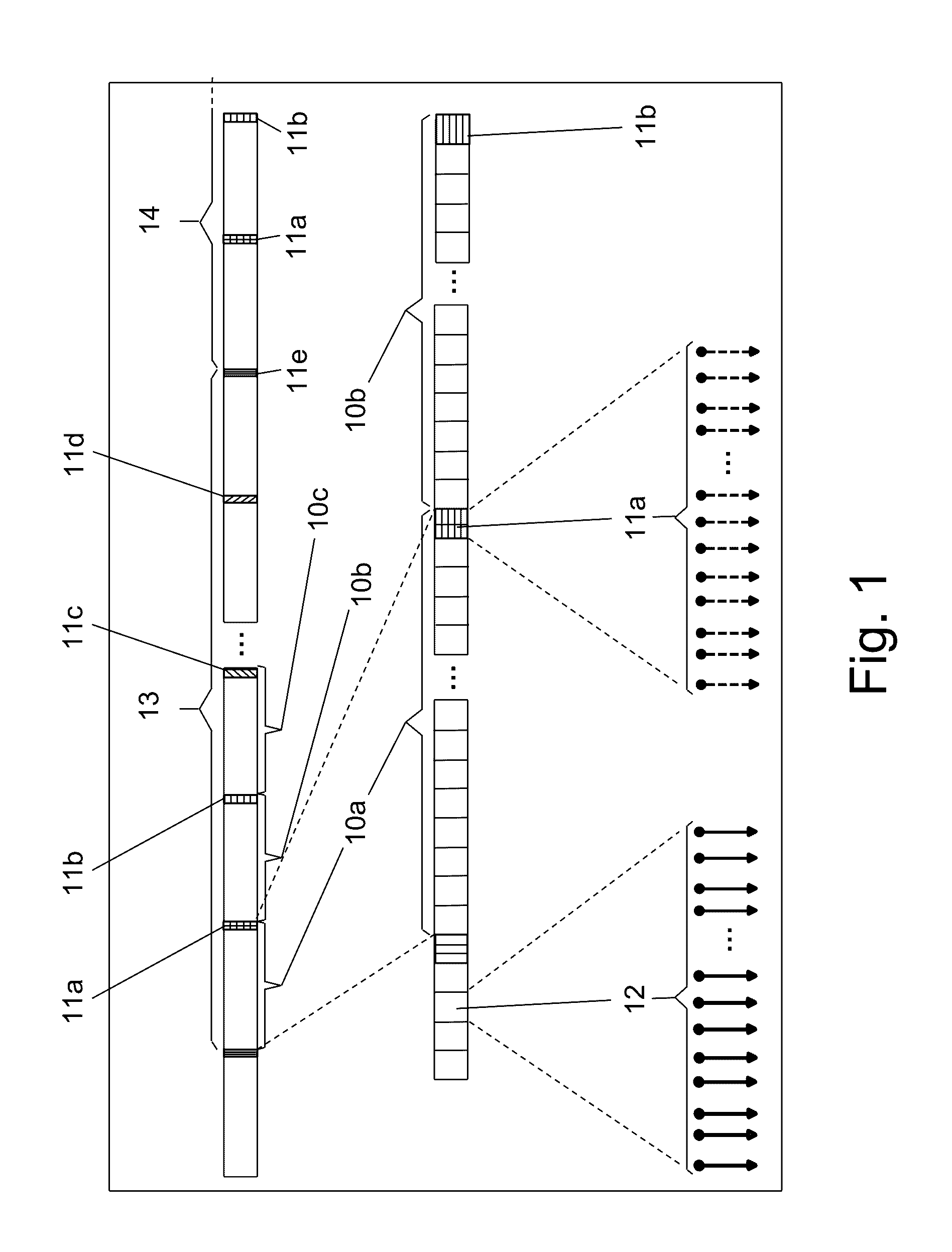
[0025]The solution proposed by the present invention uses a set of training sequences, which are periodically added to the transmitted data (to the symbols). This is done by performing the following steps, which add required signals to the raw data (symbols) as overhead. At the first step, an appropriate Forward Error Correction (FEC—a technique used for controlling errors in data transmission over unreliable or noisy communication channels) circuit is added to the transmitter as internal channel code redundancy. The added FEC circuit improves the overall sensitivity and may reduce the requirements from other equalization elements. At the second step, the data to be transmitted is segmented by dividing it into groups of symbols called segments. The symbols from one segment are transmitted one af...


PUM


Abstract

An optical communication system with nonlinear equalization capability for equalizing distortions of a data communication channel, which comprises a processor for periodically gathering a predetermined number of consecutive data segments from an input data stream to a group and adding a known pilot sequence to the group, thereby forming a data frame; an optical transmitter at the input of the channel, for transmitting the data frames to a receiver, over the channel; a receiver at the output of the channel, for detecting the transmitted frames, the receiver including a demodulator. The demodulator is adapted to recover the pilot sequence of each frame; compare each recovered pilot sequence which its corresponding original transmitted pilot sequence; extract the current Channel State Information indicative of changes in the channel distortion, using the comparison results; use changes in the Channel State Information for updating the coefficients of the estimator and of the equalizer, every time a frame is received; and equalize the channel estimator and of said equalizer, every time a frame is received; and equalize the channel using the equalizer coefficients, and based on the current Channel State Information.

Description

CROSS-REFERENCE TO RELATED APPLICATION[0001]This application claims the benefit of U.S. Provisional Application No. 62 / 172,288, filed Jun. 8, 2015, the disclosure of which is incorporated herein by reference in its entirety.FIELD OF THE INVENTION[0002]The present invention relates to the field of high-speed communication systems. More particularly, the invention relates to a framing scheme for continuous optical transmission systems.BACKGROUND OF THE INVENTION[0003]Optical and other high-speed communication channels suffer from dispersion which changes the shape of pulses which encode symbols being transmitted. Dispersion and pulse shape changes arise from the fact that different frequency components propagate at different velocities. This phenomenon causes Inter-Symbol Interference (ISI) between neighboring pulses, and ISI limits the number of discrete amplitude levels for symbol pulses which can be successfully detected. Equalization is a way of eliminating or reducing ISI.[0004]I...

Claims


Application Information

Patent Timeline
IPC IPC(8): H04L25/03H04B10/27H04L5/00H04L1/06H04B10/58H04B10/66
CPCH04L25/03019H04B10/58H04B10/27H04L5/0048H04L1/0693H04B10/66H04L25/0228H04L25/03114H04L25/03146H04B10/2507
Inventor VIDAL, OR
Owner MULTIPHY
Why Eureka
Try Eureka