
Pruning shears

a pruning shear and shear technology, applied in the field of pruning shears, can solve the problems of shortening affecting the operation affecting the overall service life of the pruning shear, so as to improve the operational smoothness and enhance the structural strength

Inactive Publication Date: 2016-12-01
LIN THOMAS
View PDF6 Cites 6 Cited by
  • Summary
  • Abstract
  • Description
  • Claims
  • Application Information

AI Technical Summary

Benefits of technology

The present invention provides a pair of pruning shears with improved smooth operation and strength. The shears have a unique design that allows for smooth cutting and a striking force between the blades. The gear mechanism is designed to push the blades closed when the handle is pulled away from the first blade, and to push the blades open when the handle is pushed towards the first blade. This allows for precise and efficient pruning.

Problems solved by technology

However, in addition to inferior operational smoothness, the prior-art device has a problem that the movable pivot shaft tends to get worn when moving between those pivot-point-forming sockets over long-term use.
Such structural weakness can shorten the overall service life of the pruning shears.

Method used


Image

  • Pruning shears
  • Pruning shears
  • Pruning shears

Examples


first embodiment

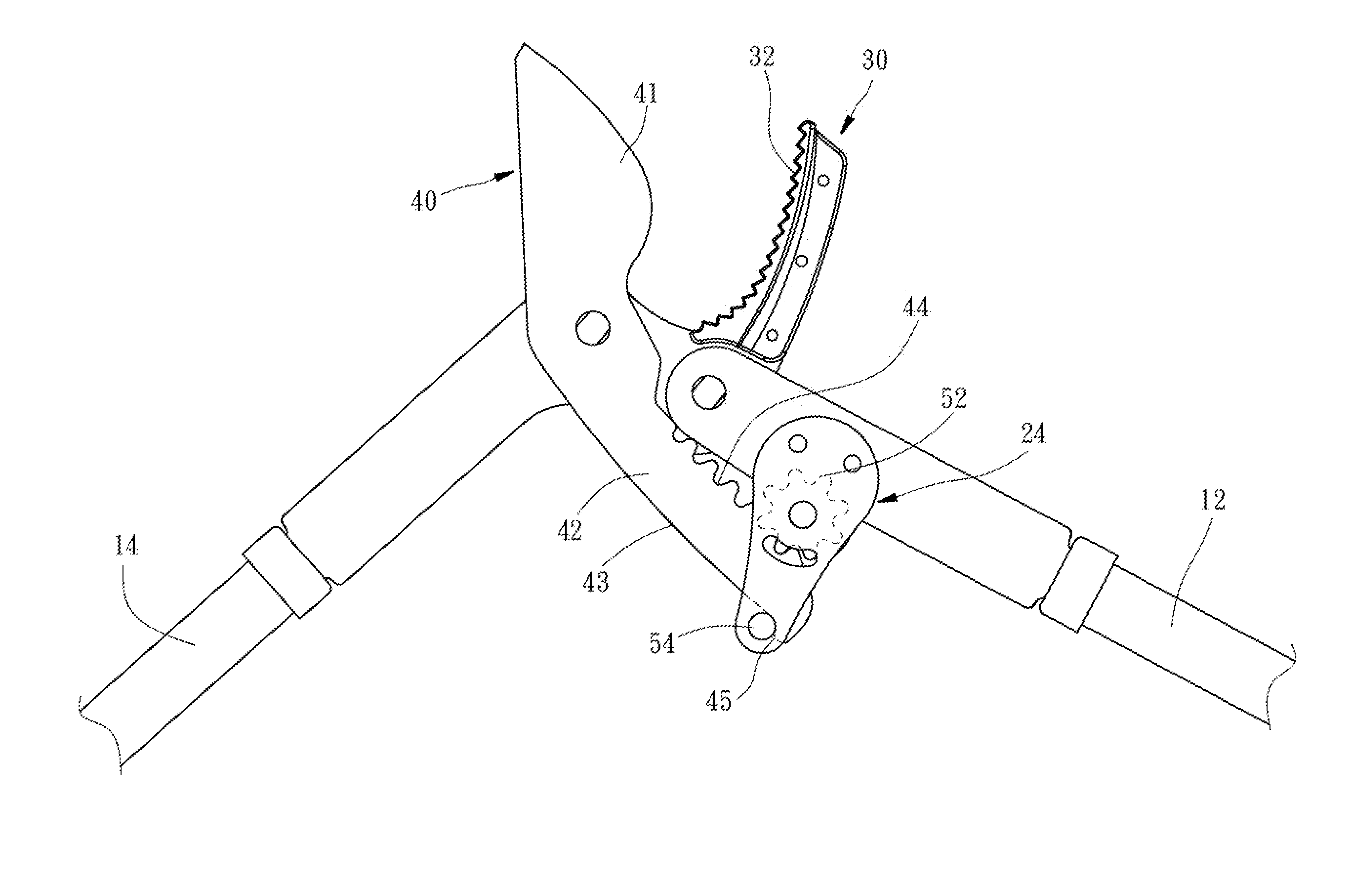
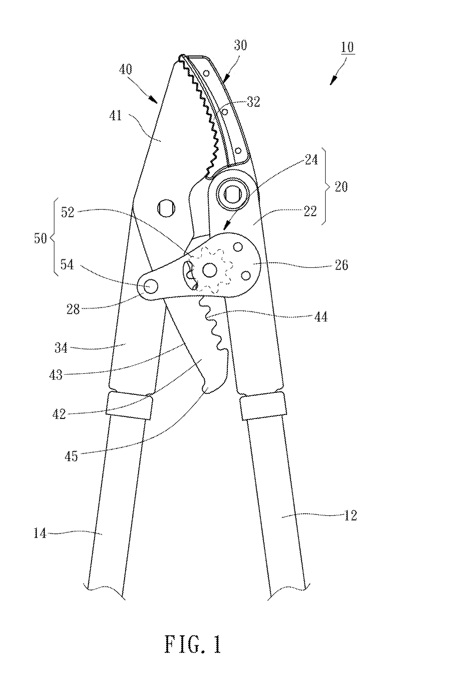
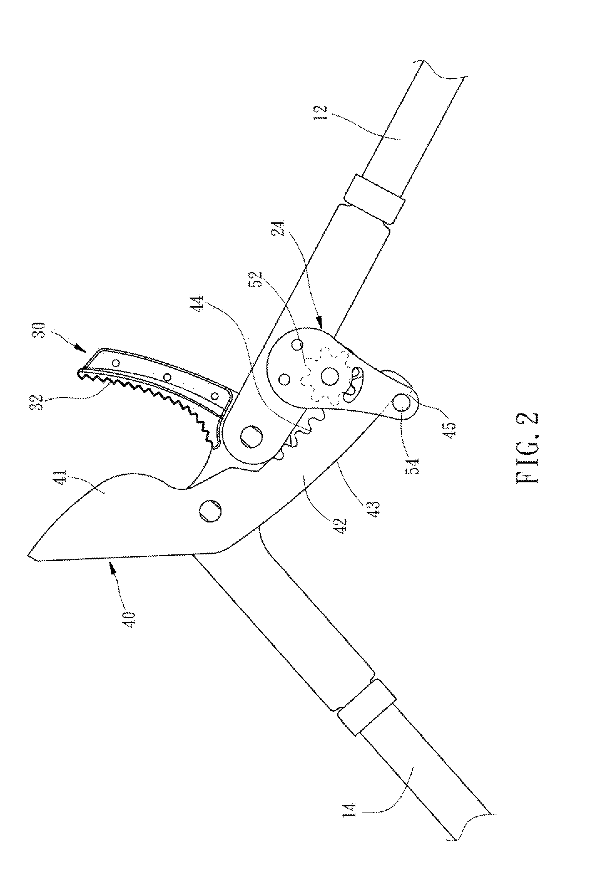
[0013]Referring to FIG. 1, according to the present invention, a pair of pruning shears 10 comprises a handle 20, a first blade 30, a second blade 40, and a controlling unit 50.

[0014]The handle 20 in the present embodiment has a handle body 22 and two opposite covers 24. The handle body 22 has its lower end fixed to an upper end of a grip 12. Each of the cover 24 includes a fixed end 26 and an over-hanging end 28. Each of the covers 24 has its fixed end 26 screwed onto an upper end of the handle body 22.

[0015]The first blade 30 includes a first cutting edge 32 and a first hilt 34. The first cutting edge 32 has its lower end pivotally connected to an upper end of the handle 20. The first hilt 34 has its upper end angled and connected to the lower end of the first cutting edge 32. The first hilt 34 has its lower end fixed to another grip 14.

[0016]The second blade 40 is pivotally connected to the first hilt 34 of the first blade 30 and has a second cutting edge 41 and a second hilt 42....

third embodiment

[0021]The controlling unit 50 is applicable to other types of pruning shears 70 (such as a pair of flower scissors as shown in FIG. 4). In the depicted third embodiment, the gear 52 is located inside the upper end of the handle 72, while a pushing member 54 is a spring instead of a pin and is located inside the first hilt 84 of the first blade 80. In addition, the pushing member 54 has its one end fixed to the first hilt 84 of the first blade 80 and an opposite end pressing against the abutting surface 96 of the second hilt 94 of the second blade 90, so as to apply a pushing force to the second hilt 94 of the second blade 90 and thereby maintain a separated state between the first cutting edge 82 of the first blade 80 and the second cutting edge 92 of the second blade 90. Thus, a user has to overcome the springiness of the pushing member 54 (i.e. the spring) before the first cutting edge 82 of the first blade 80 and the second cutting edge 92 of the second blade 90 can be drawn toge...


PUM


Abstract

A pair of pruning shears includes a handle, a first blade, a second blade, and a controlling unit. The first blade is pivotally connected to an upper end of the handle. The second blade is pivotally connected to the first blade and has a second cutting edge and a second hilt. The second hilt is connected to a lower end of the second cutting edge and has an abutting surface and a series of sockets located opposite to the abutting surface. The controlling unit has a gear and a pushing member. The gear is mounted on handle and meshes with the sockets of the second hilt of the second blade. The pushing member pushes upon the abutting surface of the second hilt of the second blade. Thereby, the first and second blades cut with improved smoothness, and the overall structural strength of the pruning shears is enhanced.

Description

BACKGROUND OF THE INVENTION[0001]1. Technical Field[0002]The present invention relates to pruning shears, and more particularly to a pair of pruning shears with enhanced structural strength.[0003]2. Description of Related Art[0004]In a known pair of pruning shears invented by the inventor of the present invention and disclosed in Taiwan Patent No. M291207, a movable pivot shaft is configured to engage with sockets located at different sites for changed pivot points, so that a user can apply force in several stages during cutting, thereby achieving labor-saving operation.[0005]However, in addition to inferior operational smoothness, the prior-art device has a problem that the movable pivot shaft tends to get worn when moving between those pivot-point-forming sockets over long-term use. Such structural weakness can shorten the overall service life of the pruning shears.BRIEF SUMMARY OF THE INVENTION[0006]The primary objective of the present invention is to provide a pair of pruning sh...

Claims


Application Information

Patent Timeline
Patent Type & Authority Applications(United States)
IPC IPC(8): A01G3/02B26B13/28
CPCB26B13/28A01G3/021
Inventor LIN, THOMAS
Owner LIN THOMAS
Learn More