
Remote Control Tool Assembly For Use In Live Line Environments

Inactive Publication Date: 2016-11-24
TAMM CARL RUSSEL
View PDF17 Cites 18 Cited by
  • Summary
  • Abstract
  • Description
  • Claims
  • Application Information

AI Technical Summary

Benefits of technology

This patent is about a tool body assembly for a remote control tool used in live line environments. This assembly includes a case assembly and a frame spine member that is positioned between the case assembly's halves. The frame spine member has a primary body with a flat upper surface and a curved lower surface. The assembly also includes a battery pack and a battery cover that form a Faraday cage around the battery. The tool body assembly is designed to be balanced and has a conductive paint and rubber boot to protect the battery. The technical effects include improved stability and protection of the battery and control circuitry, as well as better weight balance and durability of the tool.

Problems solved by technology

Problematically, in each such situation, there are limitations.
First, with hand tools, there are limitations as to the amount of torque or force that can be applied, and also difficulty with respect to having the strength to articulate the tools through a desired articulation.
With respect to the hydraulically powered tools, there have been other problems.
First, the tools themselves are quite heavy.
In turn, it is difficult for a lineman to properly control the tool at the opposite end of the insulated pole.
For these reasons, the hydraulically powered tools have not been well received.

Method used


Image

  • Remote Control Tool Assembly For Use In Live Line Environments
  • Remote Control Tool Assembly For Use In Live Line Environments
  • Remote Control Tool Assembly For Use In Live Line Environments

Examples


Embodiment Construction

[0045]While this invention is susceptible of embodiment in many different forms, there is shown in the drawings and described herein in detail a specific embodiment with the understanding that the present disclosure is to be considered as an exemplification and is not intended to be limited to the embodiment illustrated.

[0046]It will be understood that like or analogous elements and / or components, referred to herein, may be identified throughout the drawings by like reference characters. In addition, it will be understood that the drawings are merely schematic representations of the invention, and some of the components may have been distorted from actual scale for purposes of pictorial clarity.

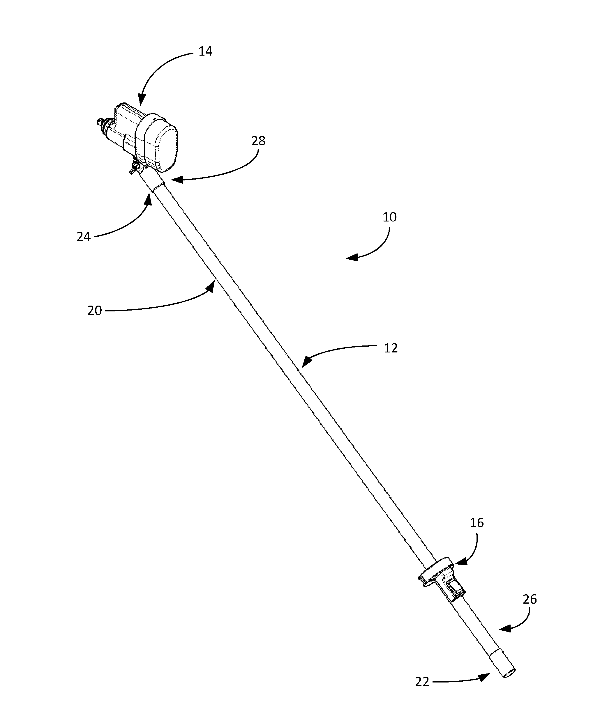
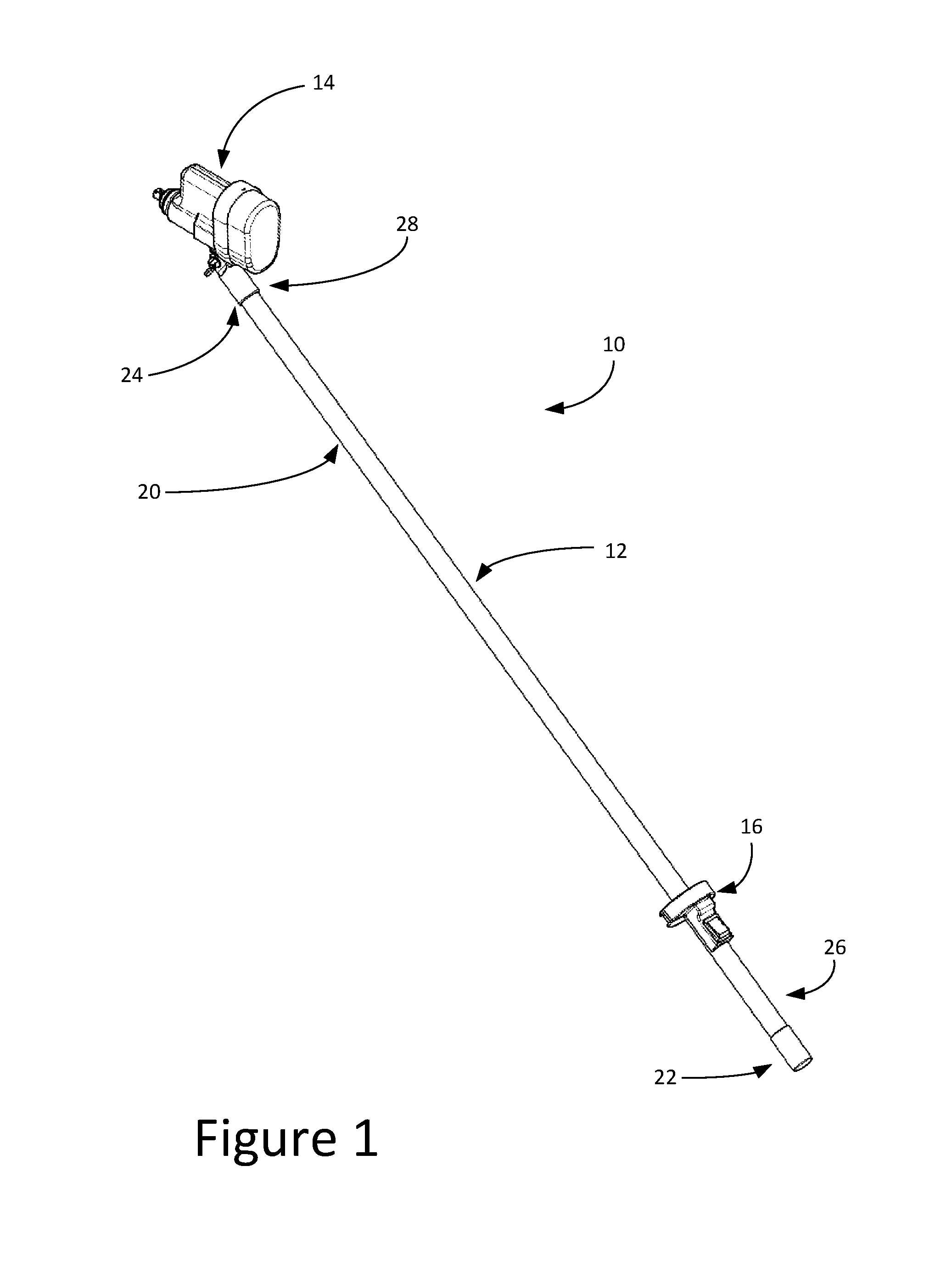
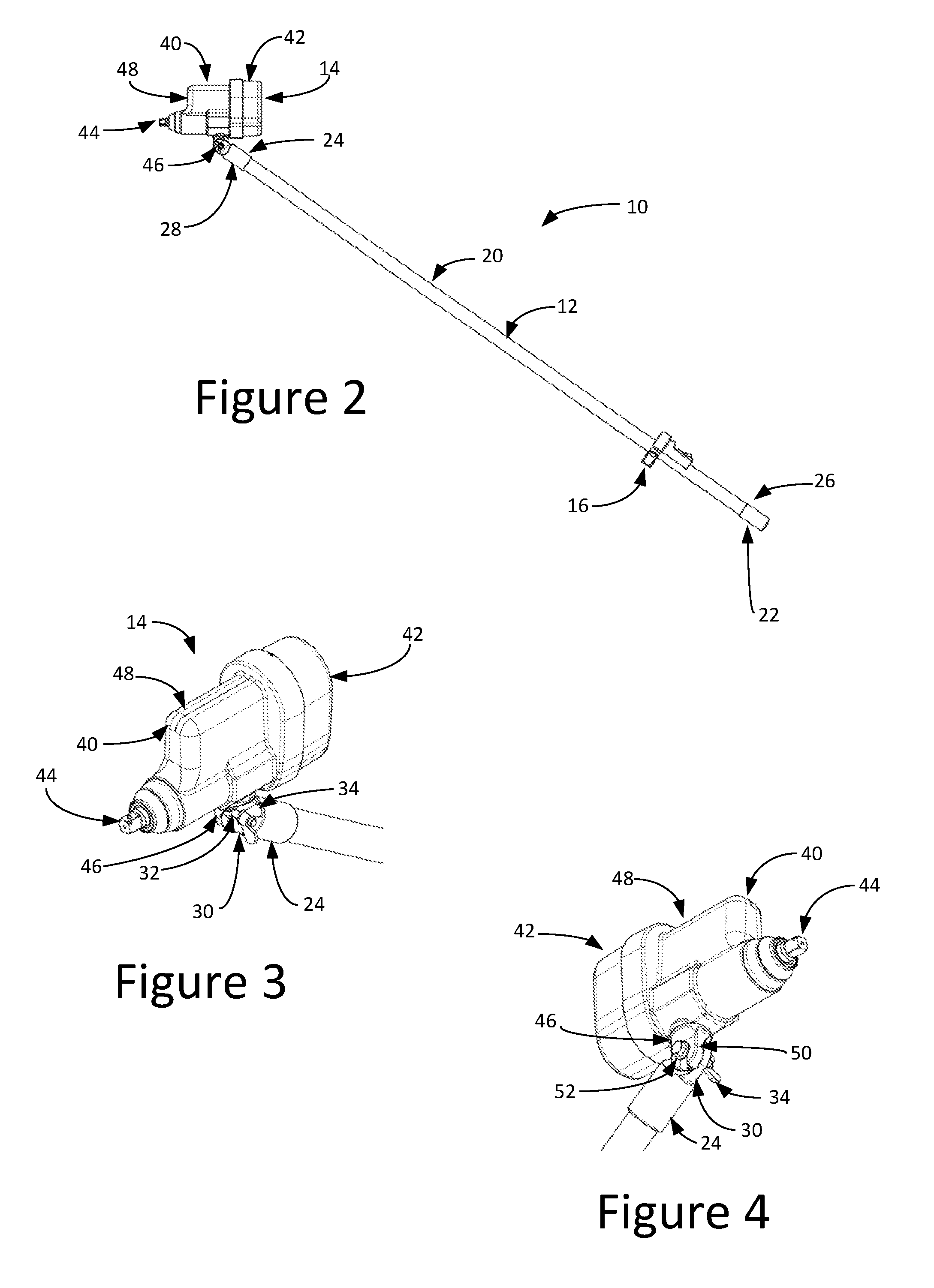
[0047]Referring now to the drawings and in particular to FIG. 1, remote control tool assembly for live line environments is shown as 10. It will be understood that such a tool has utility in a live line environment by providing a powered tool at one end that is fully electrically isolated fro...


PUM


Abstract

A remote control tool assembly for use in live line environments having an insulated pole (often termed a “hot stick”) with a tool at one end that generally includes a power supply so that the tool is fully isolatable at the end of the insulated pole. At the other end, a tool control transmitter is positioned which is configured to communicate wirelessly with the tool. Thus, the user can operate the tool remotely from the tool controller, which is particularly useful in a live line environment. A tool body assembly and a tool having a tool body assembly is disclosed.

Description

CROSS REFERENCE TO RELATED APPLICATION[0001]This application is a continuation-in-part of U.S. patent application Ser. No. 13 / 650,215, filed Oct. 12, 2012, entitled “Remote Control Tool Assembly For Use In Live Line Environments,” the entire specification of which is hereby incorporated by reference in its entirety.BACKGROUND OF THE DISCLOSURE[0002]1. Field of the Disclosure[0003]The disclosure relates in general to a remotely operated device, and more particularly, to a remote control tool assembly. The tool assembly is well suited for operations in live line environments, where insulation of a user (i.e., lineman) is well needed. Of course, the assembly is not limited for use in such an environment, and may have utility in other environments.[0004]2. Background Art[0005]The need to maintain high voltage transmission and distribution equipment, apparatuses and lines is well known in the art. It is known that in many applications, the devices must be serviced and / or maintained while...

Claims


Application Information

Patent Timeline
IPC IPC(8): H02G1/00H02G1/02B25F5/02
CPCH02G1/005H02G1/02B25F5/02
Inventor TAMM, CARL RUSSEL
Owner TAMM CARL RUSSEL
Learn More