
Sonar systems and methods using interferometry and/or beamforming for 3D imaging

Active Publication Date: 2016-11-24
NAVICO HLDG
View PDF0 Cites 50 Cited by
  • Summary
  • Abstract
  • Description
  • Claims
  • Application Information

AI Technical Summary

Benefits of technology

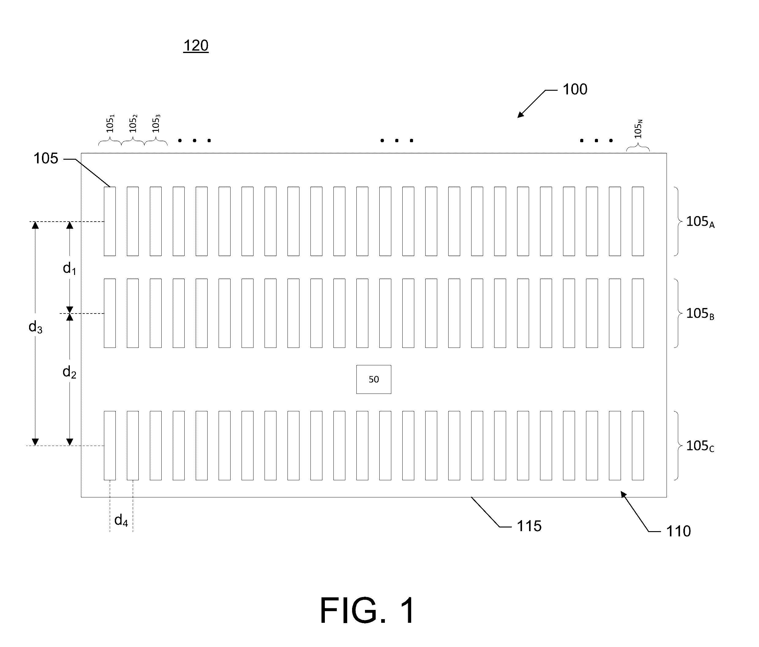
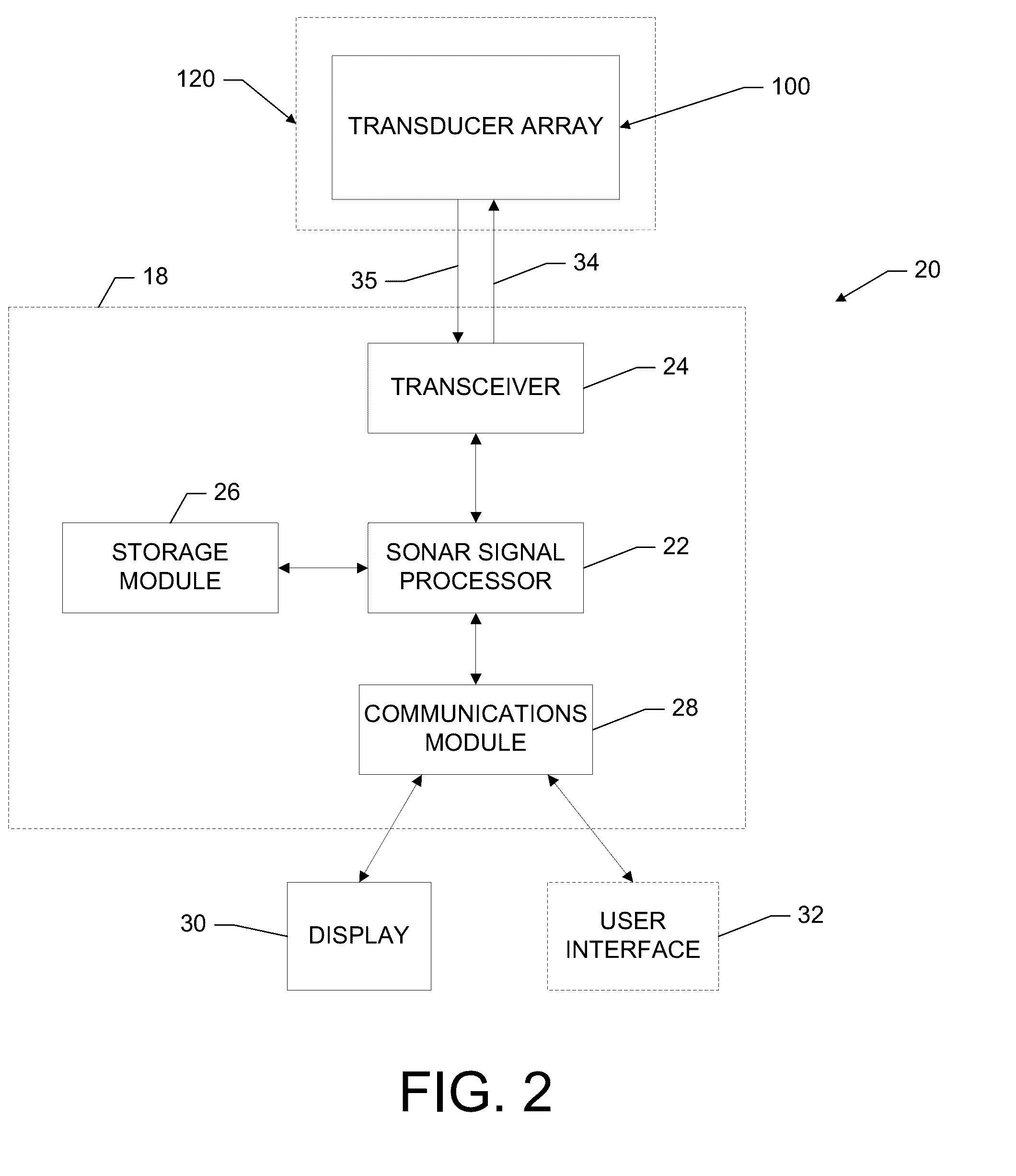
The patent describes sonar systems, transducer assemblies, and methods for imaging an underwater environment. The sonar system includes a housing with a transducer array consisting of rows of transducer elements. The first and second rows of transducer elements are positioned at a predetermined distance from each other. The system generates sonar pulses and receives sonar returns to create a 3D sonar return data set. The system uses interferometry to determine the angle of the sonar returns and position them in three dimensions. The sonar system can generate a 3D image of the underwater environment by processing the sonar return data. The technical effects of the patent include improved sonar imaging and positioning in three dimensions, as well as improved interferometric imaging.

Problems solved by technology

Applicant has identified a number of deficiencies and problems associated with conventional sonar systems and other associated systems.

Method used


Image

  • Sonar systems and methods using interferometry and/or beamforming for 3D imaging
  • Sonar systems and methods using interferometry and/or beamforming for 3D imaging
  • Sonar systems and methods using interferometry and/or beamforming for 3D imaging

Examples


Embodiment Construction

[0060]Exemplary embodiments of the present invention now will be described more fully hereinafter with reference to the accompanying drawings, in which some, but not all embodiments of the invention are shown. Indeed, the invention may be embodied in many different forms and should not be construed as limited to the exemplary embodiments set forth herein; rather, these embodiments are provided so that this disclosure will satisfy applicable legal requirements. Like reference numerals refer to like elements throughout.

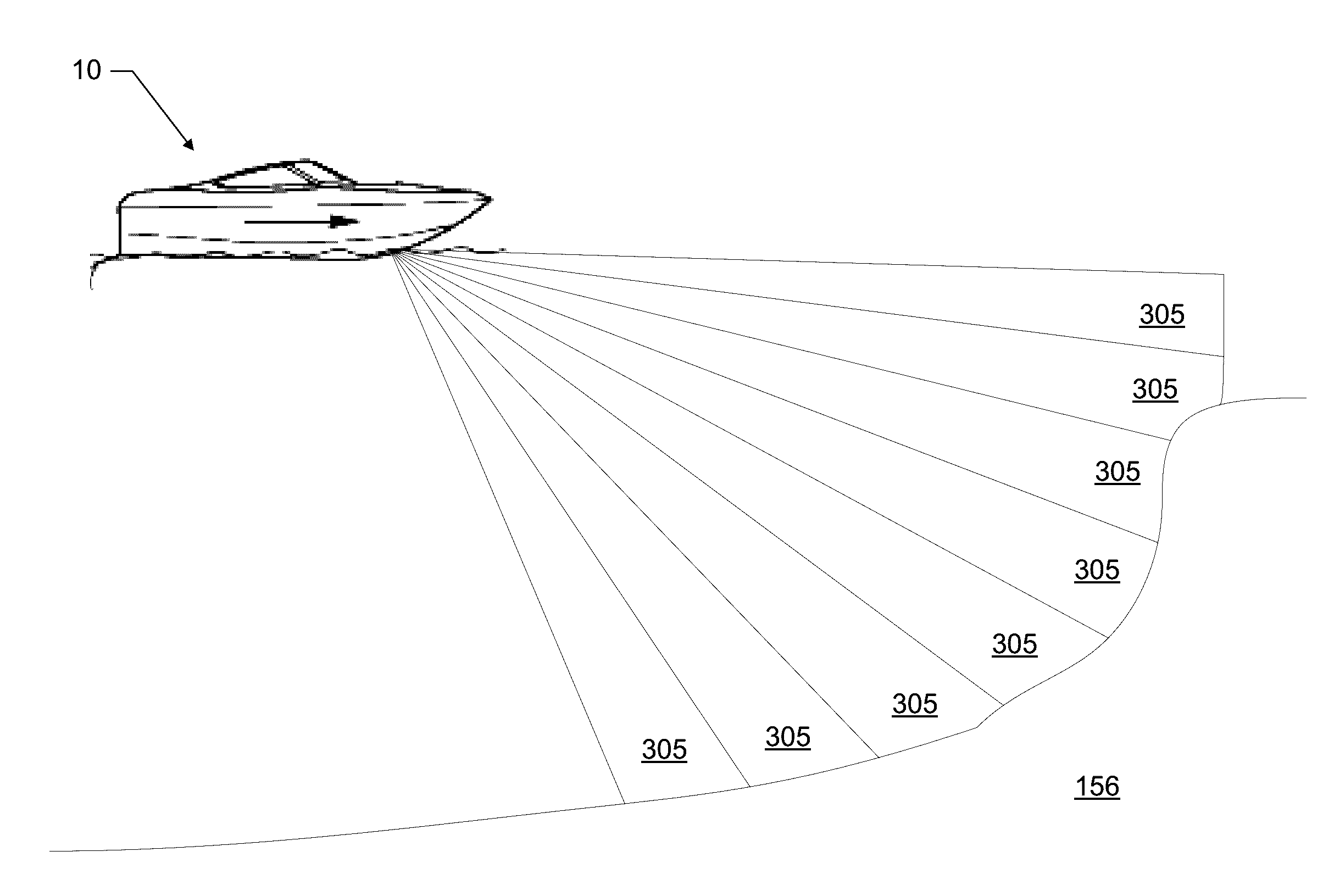
[0061]Sonar systems may transmit sonar waves into a body of water with a transmit transducer, a transmit / receive transducer, or similar device. When the sound waves strike anything of differing acoustic impedance (e.g., the sea floor or something suspended in the water above the bottom), the sound waves reflect off that object. These echoes or sonar returns may strike a sonar transducer or a separate sonar receiver element, which converts the echoes back into an electri...


PUM


Abstract

Provided are a sonar system, transducer assembly, and method for imaging an underwater environment. The sonar system may include a housing having a transducer array defining first and second rows of transducer elements positioned at a predetermined distance. The first row of transducer elements may include at least first and second transducer elements configured to convert sound energy into first and second sonar return data. The second row of transducer elements may include at least third and fourth transducer elements configured to convert sound energy into third and fourth sonar return data. A sonar signal processor may be configured to process the first and second sonar return data and third and fourth sonar return data to generate respective first and second array sonar return data corresponding to a plurality of first and second receive beams and generate 3D sonar return data by correlating the angles associated with the receive beams.

Description

FIELD OF THE INVENTION[0001]Embodiments of the present invention relate generally to sonar systems and, more particularly, to sonar systems, assemblies, and associated methods that use interferometry and / or beamforming for producing a 3D image or one or more 2D images of an underwater environment.BACKGROUND OF THE INVENTION[0002]Sonar (SOund Navigation And Ranging) has long been used to detect waterborne or underwater objects. For example, sonar devices may be used to determine depth and bottom topography, detect fish, locate wreckage, etc. In this regard, due to the extreme limits to visibility underwater, sonar is typically the most accurate way to locate objects underwater. Sonar transducer elements, or simply transducers, may convert electrical energy into sound or vibrations at a particular frequency. A sonar sound beam is transmitted into and through the water and is reflected from objects it encounters. The transducer may receive the reflected sound (the “sonar returns”) and ...

Claims


Application Information

Patent Timeline
IPC IPC(8): G01S15/89G01S7/62
CPCG01S7/6245G01S15/8902G01S15/89
Inventor HORNER, RONALD JOEPROCTOR, ALAN LEE
Owner NAVICO HLDG
Learn More