Distal radius plate

a technology distal radius plate, which is applied in the field of distal radius plate, can solve the problems of irritation and/or rupture of tendons in improper shape, and inability to properly center etc., and achieves the effect of reducing the cost of making and the cost and time of manufacturing, determining quickly, quickly and accurately centering the distal radius pla

Active Publication Date: 2016-11-24
EXSOMED CORP
View PDF9 Cites 11 Cited by
  • Summary
  • Abstract
  • Description
  • Claims
  • Application Information

AI Technical Summary

Benefits of technology

The invention is a distal radius plate used to secure the radius bone during surgery. The plate has two basic portions, an elongated portion and a distal radius portion, which are designed to follow the shape of the radius bone. It can be made completely of metal or metal support with plastic overlay, reducing manufacturing costs. The plate can have a straight line to help surgeons quickly and accurately center it on the radius bone. It may also have a stop to prevent over rotation of the plate. These technical effects make the distal radius plate easier and more cost-effective to manufacture and use in surgery.

Problems solved by technology

Notwithstanding its value, a well-known complication of volar plating is irritation and / or rupture of the tendons, especially flexor tendons.
Some common problems with the aforementioned prior art devices are (1) they are difficult to center on the radius bone, (2) they sometimes rotate out of being centered after first being affixed, (3) they are not shaped like the distal end of the radius and may not secure it properly, and (4) they are not shaped properly, and do not have the proper screw holes or locations, to cover every size arm / hand (or at least a large range of arm / hand sizes).

Method used


Image

  • Distal radius plate
  • Distal radius plate
  • Distal radius plate

Examples


Embodiment Construction

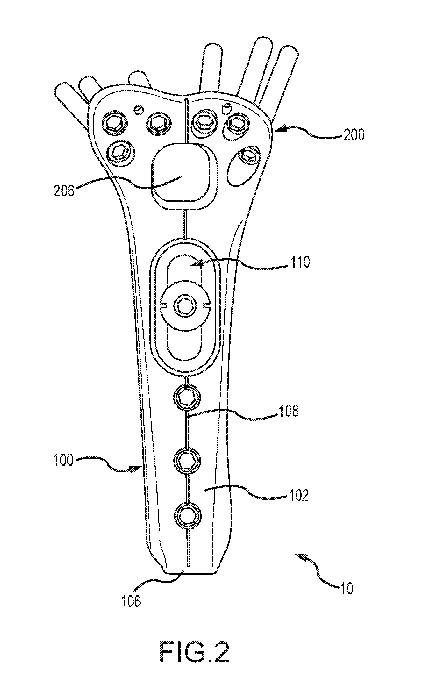
[0023]Turning now to the drawings wherein the purpose is to describe a preferred embodiment of the invention and not to limit same. FIG. 1 shows a top, perspective view of a distal radius plate 10 in accordance with aspects of the invention. Distal radius plate 10 is preferably comprised of metal, such as stainless steel. Plate 10 has two main portions: elongated portion 100 and distal radius portion 200. Elongated portion 100 has a top side 102, a bottom side 104 and a distal end (or end) 106. Top side 102 is smooth and has a centerline 108 stamped or otherwise formed therein, or centerline 108 could be printed. A slot 110 is formed in portion 100 and has an upper opening 112, which is large enough to receive and retain a screw head, and a lower opening 114, which is large enough for a screw body to pass through and thread into the body of the radius bone, but too small for the screw head to pass through.

[0024]Between slot 112 and end 106 are three first openings 116 shown as being...


PUM


Abstract

A distal radius plate according to the invention is ergonomically formed to be more easily centered on the radius bone. The distal radius plate has two main portions: an elongated portion that attaches to the body of the radius and a distal radius portion that attaches to the lower most, wider portion of the radius bone. Because of its ergonomic shape the distal radius plate is fast and easy to center on the radius and install. In another embodiment, the distal radius plate may include a metal support that is partially or entirely covered with a plastic to eliminate or reduce detailed machining of the metal, which reduces part cost and manufacturing time.

Description

CROSS-REFERENCE TO RELATED APPLICATIONS[0001]This application claims priority to U.S. Provisional Patent Application Ser. No. 62 / 163,912 entitled “DISTAL RADIUS PLATE,” filed on May 19, 2015, the disclosure of which is incorporated herein by reference.FIELD AND BACKGROUND OF THE INVENTION[0002]The forearm has two large bones, the radius and the ulna, which run parallel to one another. The proximal end of the radius is at the lateral side of the elbow and extends all the way to the thumb side of the wrist which is the distal end of the radius (from a reference position in which the palm of the hand faces forward). The radius can also be divided in its other dimensions. For example the palm side of the radius bone is called the “volar” and the other side is called “dorsal.” The volar distal radius therefore refers to the palm side of the distal radius. The most prominent region (the part that sticks out like a ridge line) of the volar distal radius is called the “watershed line.” A di...

Claims


Application Information

Patent Timeline
IPC IPC(8): A61B17/80
CPCA61B17/8061A61B2017/681A61B17/8014A61B17/80A61B17/8004A61B17/809
Inventor CHAMPAGNE, LLOYD P.ZOLDOS, JOZEF
Owner EXSOMED CORP
Why Eureka
Try Eureka