
Turbocharger with oil-free hydrostatic bearing

Active Publication Date: 2016-11-17
FLORIDA TURBINE TECH
View PDF4 Cites 0 Cited by
  • Summary
  • Abstract
  • Description
  • Claims
  • Application Information

AI Technical Summary

Benefits of technology

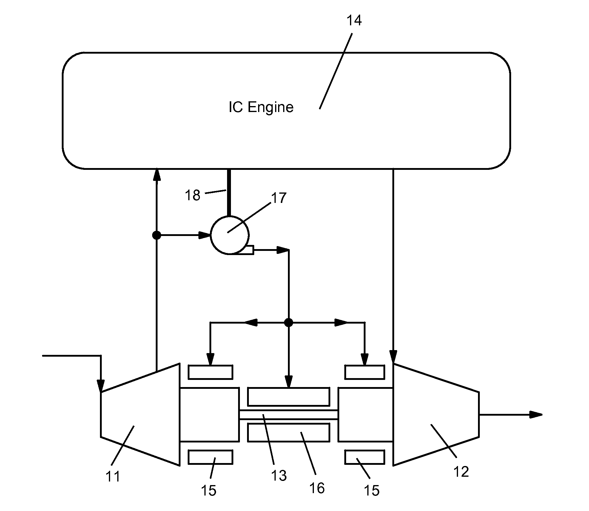
This patent is about a new type of bearing that is used in a turbocharger for light weight aircraft. These bearings are made without any fluid and use compressed air from a compressor and boost pump to handle higher temperatures. This helps to reduce the weight of the turbocharger and improve its performance.

Problems solved by technology

If oil pressure is lost or if the oil becomes contaminated from the internal combustion (IC) engine, degradation in bearing performance due to loss of lubrication or cooling occurs, leading to catastrophic failure of the turbocharger bearing system.

Method used


Image

  • Turbocharger with oil-free hydrostatic bearing
  • Turbocharger with oil-free hydrostatic bearing

Examples


Embodiment Construction

[0012]The present invention is a turbocharger with an oil-free hydrostatic bearing. The compressor discharge gas is used as the working fluid for the hydrostatic bearing with a boost compressor to achieve sufficient hydrostatic load capacity and damping in the bearings. The present invention improves reliability and durability by eliminating the temperature sensitive oil lubricant, the oil cooler, the oil pump and bearing housing cooling systems of the prior art turbochargers. This is accomplished by utilizing compressed gas (air) from the compressor to support the shaft hydrostatically. To reduce overall power consumption in the system, the bearing feed system is pre-boosted by the turbocharger compressor and then boosted to the required operating pressure using an oil-free positive displacement compressor that is either driven directly off of the engine through an accessory take-off or driven by a small electric motor. In either case, the total power draw is relatively small resul...


PUM


Abstract

A turbocharger for an internal combustion engine, the turbocharger being supported by hydrostatic bearings in both a radial and an axial direction by a compressed air supplied from a compressor of the turbocharger and boosted in pressure by a separate boost pump to a high enough pressure to support the rotor of the turbocharger.

Description

CROSS-REFERENCE TO RELATED APPLICATIONS[0001]This application claims the benefit to a Provisional Application 61 / 881,667 filed on Sep. 24, 2013 and entitled TURBOCHARGER WITH OIL-FREE HYDROSTATIC BEARING.GOVERNMENT LICENSE RIGHTS[0002]None.BACKGROUND OF THE INVENTION[0003]1. Field of the Invention[0004]The present invention relates generally to a turbocharger, and more specifically to a turbocharger with an oil-free hydrostatic bearing.[0005]2. Description of the Related Art including information disclosed under 37 CFR 1.97 and 1.98[0006]A turbocharger is used to compress air supplied to an engine using a hot gas exhaust as a driving force. The engine exhaust drives a turbine that drives a compressor to supply the compressed air to the engine. The performance of the engine is increased due to the compressed air.[0007]Prior art turbochargers require shaft support systems that use oil lubricated bearings which depend on the viscosity of the fluid to provide a hydrodynamic film in the ...

Claims


Application Information

Patent Timeline
IPC IPC(8): F01D25/22F02B37/04
CPCF02B37/04F01D25/22F05D2220/40
Inventor MILLER, TIMOTHY JPINERA, ALEX
Owner FLORIDA TURBINE TECH
Learn More