
Direction-adaptive image deblurring method

a direction-adaptive, image-deblurring technology, applied in image enhancement, image analysis, instruments, etc., can solve the problems of increasing the difficulty of post-operation such as target positioning and target categorizing, affecting the speed of the algorithm, and affecting the accuracy of the algorithm, etc., to achieve excellent adaptability

Active Publication Date: 2016-11-03
HUAZHONG UNIV OF SCI & TECH
View PDF0 Cites 16 Cited by
  • Summary
  • Abstract
  • Description
  • Claims
  • Application Information

AI Technical Summary

Benefits of technology

The objective of this patent is to provide a method that can quickly and effectively deblur images in remote imaging with a small amount of computation and good adaptability. The method uses a new direction-adaptive cost function that solves the problem of traditional TV regularization terms being blurred. It can restore images of different blurring types and with complex textures. Overall, the invention offers an improved solution to image blurring issues.

Problems solved by technology

Targets in images obtained by sensors tend to be blurred due to limited spacial resolution of a camera and interference of random noise and atmospheric turbulence with a remote optical imaging system, which makes post operations such as target positioning and target categorizing quite difficult, and therefore, how to improve imaging quality of the images becomes a focus of research both at home and abroad.
However, the method mainly targets at infrared imaging in turbulence and correction on remote visible imaging is not covered.
21 (2010) 193˜199 proposes a rapid image deblurring method based on split Bregman techniques which can only improve velocity of the algorithm and fails to improve correction quality of the images.

Method used


Image

  • Direction-adaptive image deblurring method
  • Direction-adaptive image deblurring method
  • Direction-adaptive image deblurring method

Examples


Embodiment Construction

[0019]For clear understanding of the objectives, features and advantages of the invention, detailed description of the invention will be given below in conjunction with accompanying drawings and specific embodiments. It should be noted that the embodiments are only meant to explain the invention, and not to limit the scope of the invention.

[0020]Various solutions to the problem of image deblurring with respective algorithm features have been developed in prior art. However, the algorithms deduce optimal solutions statistically or approximately merely by certain large-scaled priori features of the images in statistics failing to use small-scaled geometric and structural features of the images such as edge directions and texture directions to constraint and correct the results. Therefore, boundary blur and detail lost often occur in edges of the deblurred images. In view of the above-mentioned problems, there is provided a direction-adaptive image deblurring method introducing small-s...


PUM


Abstract

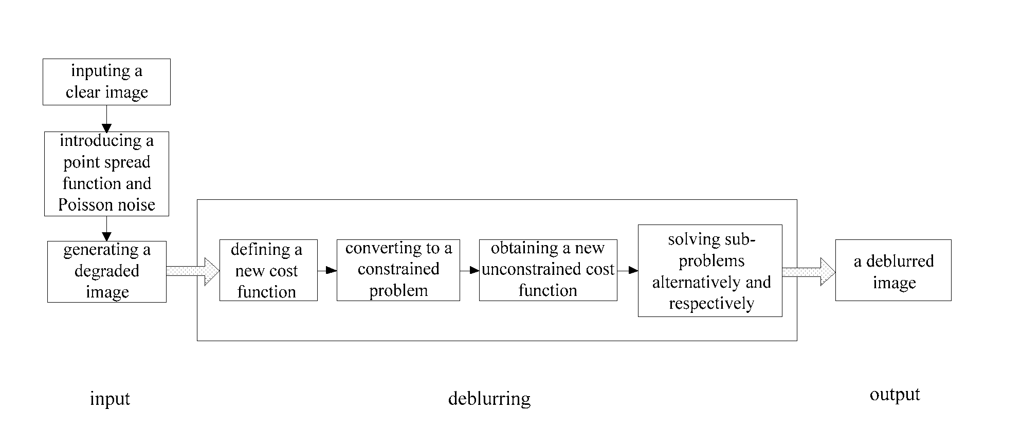
The invention discloses a direction-adaptive image deblurring method, comprising steps of: (1) defining a minimum cost function for deblurring an image by direction-adaptive total variation regularization; (2) converting the unconstrained minimization problem in step (1) to a constrained problem by auxiliary variables d1=Hu, d2=∇xu and d3=∇yu; (3) obtaining a new minimum cost function from the constrained problem in step (2) by introducing penalty terms; and (4) converting the minimization problem in step (3) to an alternating minimization problem about u, d1, d2 and d3, where a minimum of a variable is calculated as other variables are determined, and obtaining a deblurred image by solving the alternating minimization problem by an alternative and iterative minimization process. Compared with the prior art, the present invention obtains a new direction-adaptive cost function by introducing local direction information into a maximum a posteriori algorithm, solves a problem of edges of an image restored by traditional TV regularization terms being blurred, and can restore images of complex blurring types or images with abundant textures.

Description

FIELD OF THE INVENTION[0001]The invention relates to a cross field of aerospace and image processing, and more particularly to a direction-adaptive image deblurring method mainly applicable for image deblurring in remote imaging.BACKGROUND OF THE INVENTION[0002]Spacial targets such as communication satellites and resources satellites launched at home and abroad can be used in network communication, aerophotography, geodesy, etc. Targets in images obtained by sensors tend to be blurred due to limited spacial resolution of a camera and interference of random noise and atmospheric turbulence with a remote optical imaging system, which makes post operations such as target positioning and target categorizing quite difficult, and therefore, how to improve imaging quality of the images becomes a focus of research both at home and abroad. Intensive studies on deblurring algorithms on targets under the above imaging conditions have been carried out and relevant achievements have been made. F...

Claims


Application Information

Patent Timeline
Patent Type & Authority Applications(United States)
IPC IPC(8): G06T5/00
CPCG06T2207/20004G06T5/003G06T2207/20012G06T2207/20056G06T5/73G06T5/00
Inventor ZHANG, TIANXUZHOU, GANGZHONG, AOWANG, LIANGLIANGLI, MINGLU, CENZHANG, WENZUO, ZHIYONG
Owner HUAZHONG UNIV OF SCI & TECH
Learn More