
Near-eye light-field display system

a technology of light-field display and near-eye display, which is applied in the field of near-eye displays, can solve the problems of low resolution of hmds and achieve the effect of increasing or reducing distan

Inactive Publication Date: 2016-10-27
GUTIERREZ ROMAN
View PDF9 Cites 41 Cited by
  • Summary
  • Abstract
  • Description
  • Claims
  • Application Information

AI Technical Summary

Benefits of technology

The patent describes a head mounted display that uses a special lens to capture light from a display and create a light field representation. This display can be used to create a realistic and immersive experience for the user. The head mounted display has an exterior and interior housing for the lens and display arrays, and a vertical motion actuator that can adjust the distance between the two arrays. The technical effects include improved image quality and a more realistic visual experience for the user.

Problems solved by technology

Despite the use of optics, however, HMDs generally have low resolution because of trade-offs related to the overall weight and form factor of the HMD, as well as pixel pitch.

Method used


Image

  • Near-eye light-field display system
  • Near-eye light-field display system
  • Near-eye light-field display system

Examples


Embodiment Construction

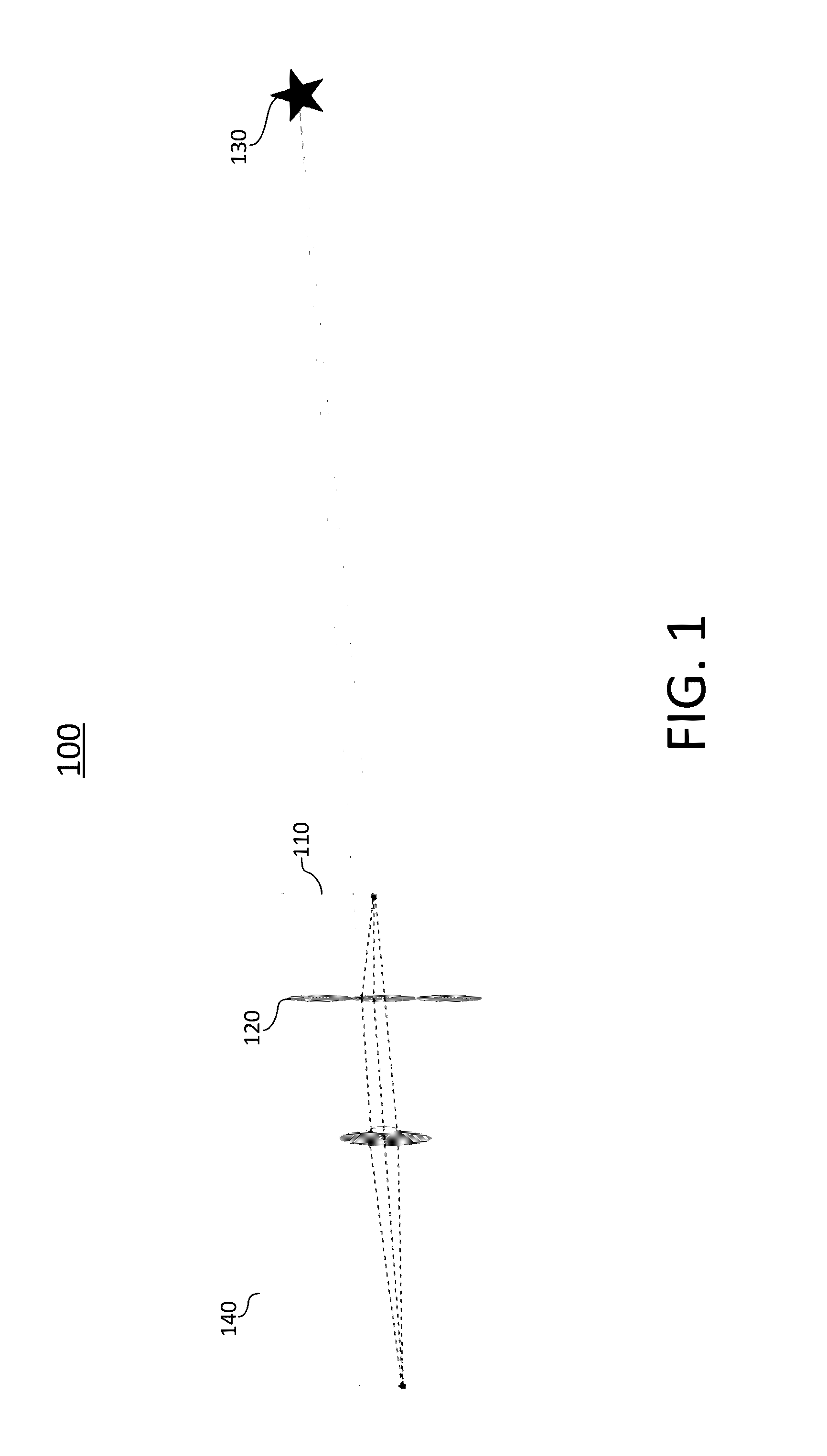
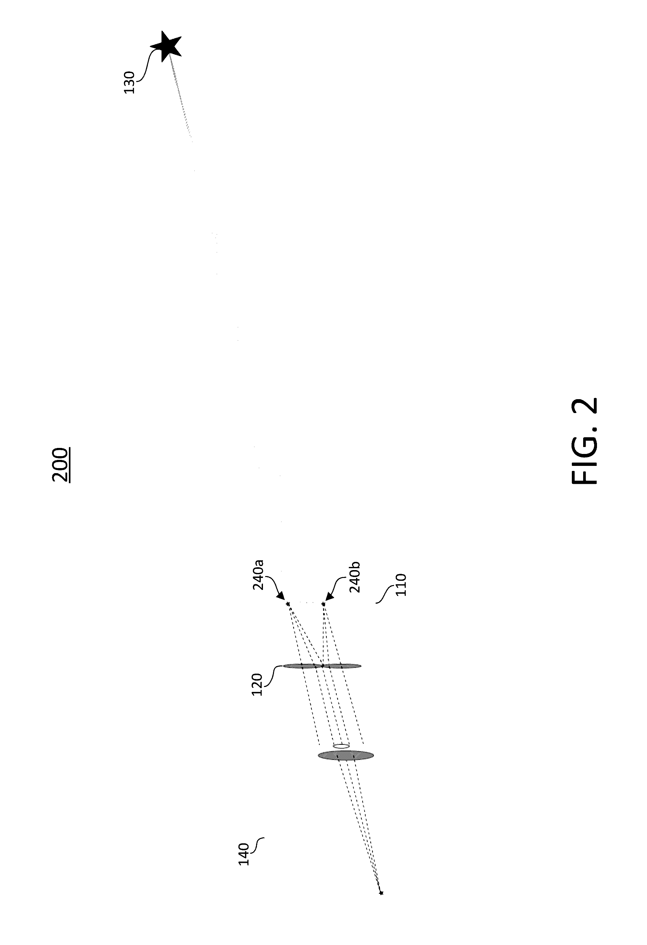
[0004]According to various embodiments of the disclosed technology, a head mounted display for generating light field representations is provided. The head mounted display comprises an array of lenses (comprising a plurality of light field lenses) positioned opposite and parallel to an array of displays (comprising a plurality of light sources). The array of lenses may be configured to capture light rays from one or more light sources of the array of displays to generate a near-eye light field representation. The head mounted display may include an exterior housing configured to support the edge of the array of lenses, and an interior housing configured to support the array of displays disposed on a surface of the interior housing. In some embodiments, the exterior housing and the interior housing may be positioned such that the distance between the array of lenses and the array of displays remains fixed. In other embodiments, a vertical motion actuator may be disposed between the i...


PUM


Abstract

A near-eye light field display for use with a head mounted display unit with enhanced resolution and color depth. A display for each eye is connected to one or more actuators to scan each display, increasing the resolution of each display by a factor proportional to the number of scan points utilized. In this way, the resolution of near-eye light field displays is enhanced without increasing the size of the displays.

Description

CROSS-REFERENCE TO RELATED APPLICATIONS[0001]This application claims the benefit of U.S. Provisional Application Ser. No. 62 / 152,893, filed Apr. 26, 2015, which is hereby incorporated herein by reference in its entirety.TECHNICAL FIELD[0002]The disclosed technology relates generally to near-eye displays, and more particularly, some embodiments relate to near-eye systems having light-field displays.DESCRIPTION OF THE RELATED ART[0003]Head-mounted displays (“HMDs”) are generally configured such that one or more displays are placed directly in front of a person's eyes. HMDs have been utilized in various applications, including gaming, simulation, and military uses. Traditionally, HMDs have comprised heads-up displays, wherein the user focuses on the display in front of the eyes, as images are traditionally displayed on a two-dimensional (“2D”) surface. Optics are used to make the display(s) appear farther away than it actually is, in order to allow for a suitable display size to be uti...

Claims


Application Information

Patent Timeline
Patent Type & Authority Applications(United States)
IPC IPC(8): G02B27/01G09G5/12
CPCG02B27/0172G02B27/0176G09G5/12G02B2027/014G02B2027/0154G02B2027/015G02B2027/0138G09G3/001G09G3/003G09G2340/0457G09G2340/145G06F3/013G09G2340/0407G09G3/02G09G2354/00G09G2360/145H02N1/008
Inventor GUTIERREZ, ROMAN
Owner GUTIERREZ ROMAN
Learn More