Spectroscopic Unit And Spectroscopic Device Using Same

a spectroscopic unit and a spectroscopic device technology, applied in the direction of optical radiation measurement, instruments, spectrometry/spectrophotometry/monochromators, etc., can solve the problems of multiple reflection within the filter, multiple reflection between, etc., and achieve the effect of reducing multiple reflection

Active Publication Date: 2016-10-27
KONICA MINOLTA INC
View PDF2 Cites 1 Cited by
  • Summary
  • Abstract
  • Description
  • Claims
  • Application Information

AI Technical Summary

Benefits of technology

[0007]The present invention is directed to providing a spectroscopic unit capable of reducing multiple-reflection which would otherwise occur within the aforementioned filter, to thereby allow each of a plurality of light-receiving elements of a light-receiving section to be reduced in terms of receiving of a light component in a wavelength band other than a specific wavelength band to be essentially received by each light-receiving element, and providing a spectroscopic device using the spectroscopic unit.
[0008]According to one aspect of the present invention, there is provided a spectroscopic unit and a spectroscopic device which includes a filter having a transmission wavelength which varies depending on an incident position along a first direction. The filter includes a plurality of optical filter elements sequentially arranged in a direction from an incident side to an output side of the target light, wherein a first optical filter element as one of the plurality of optical filter elements is rotated, by a given angle, about a rotational axis defined along a third direction orthogonal to each of the first direction and a second direction extending from the incident side toward the output side of the target light, or rotated, by a given angle, about a rotational axis defined along the first direction, and thereby disposed inclinedly with respect to a second optical filter element disposed in adjacent relation to the first optical filter element. Therefore, the spectroscopic unit and the spectroscopic device of the present invention make it possible to reduce multiple-reflection which would otherwise occur within the filter, to thereby reduce receiving of a light component in wavelength band other than a specific wavelength band to be essentially received by each light-receiving element.

Problems solved by technology

In this case, the light-receiving section reflects a part of incident light because it is incapable of fully photoelectrically converting the incident light, and thereby multiple-reflection occurs between the filter and the light-receiving section.
This leads to occurrence of multiple-reflection within the filter.

Method used


Image

  • Spectroscopic Unit And Spectroscopic Device Using Same
  • Spectroscopic Unit And Spectroscopic Device Using Same
  • Spectroscopic Unit And Spectroscopic Device Using Same

Examples


first embodiment

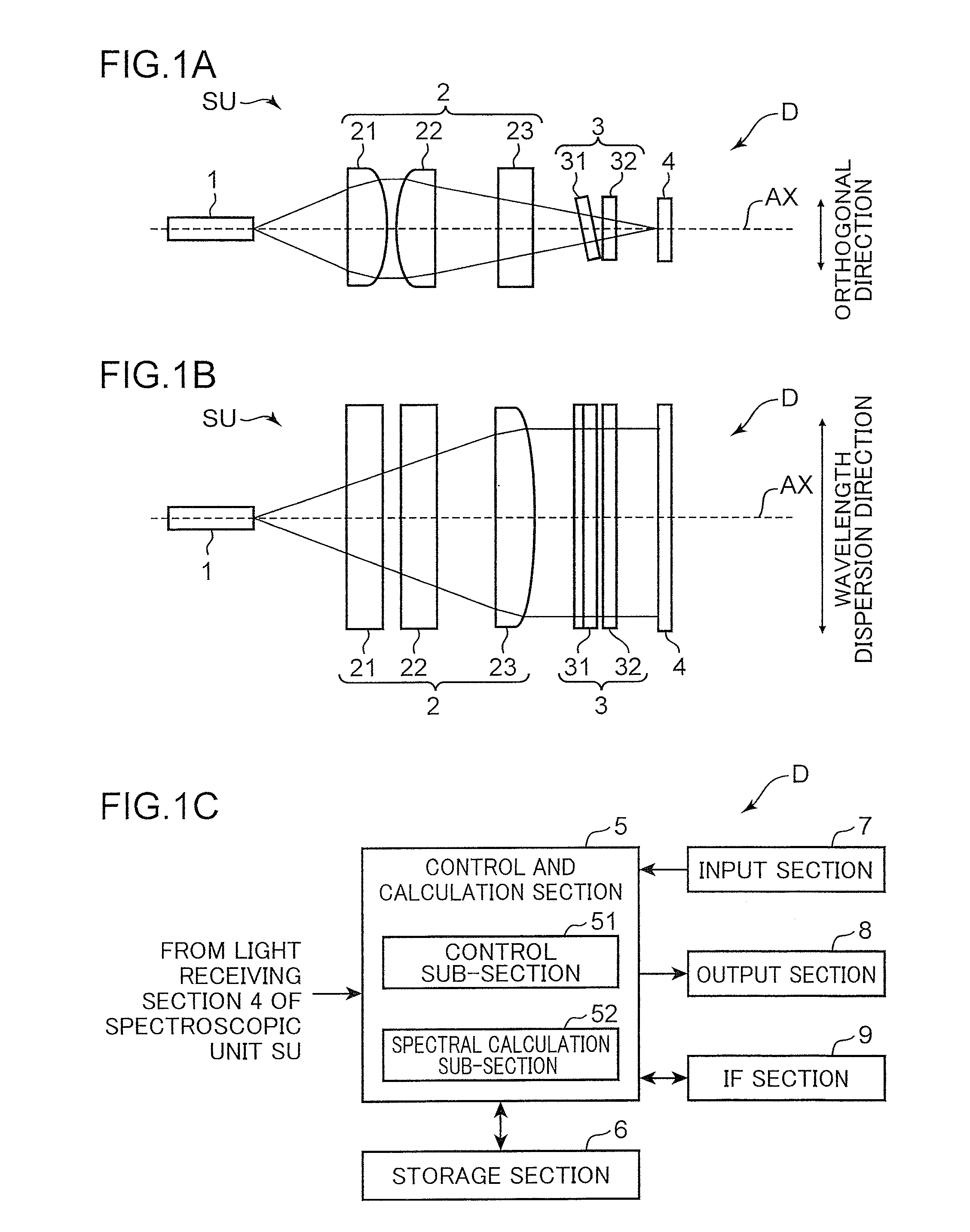
[0029]FIG. 1 is a diagram depicting a configuration of a spectroscopic device according to a first embodiment of the present invention. FIG. 1A and FIG. 1B depict, respectively, a side view of a spectroscopic unit and a top view of the spectroscopic unit, and FIG. 1C is a block diagram depicting an electrical configuration of the spectroscopic device. FIG. 2 is a fragmentary enlarged diagram depicting the configuration of the spectroscopic device according to the first embodiment. FIGS. 2A and 2C are top views, and FIGS. 2B and 2D are side views. FIGS. 2A and 2B depict a state of reflection within a filter 3, and FIGS. 2C and 2D depict a state of reflection between the filter 3 and a light-receiving section 4. FIG. 3 is an explanatory diagram of a transmission wavelength characteristic of a linear variable filter in the spectroscopic device according to the first embodiment. FIG. 3A depicts respective transmission wavelength sub-characteristic at a plurality of incident positions XP...

second embodiment

[0090]FIG. 17 is a diagram depicting a configuration of a spectroscopic unit in a spectroscopic device according to a second embodiment of the present invention. FIG. 17A is a side view depicting the spectroscopic unit, and FIG. 17B is a top view depicting the spectroscopic unit.

[0091]In the spectroscopic unit SU in the spectroscopic device D according to the first embodiment, the opening member 1, the optical system 2, the filter 3 and the light-receiving section 4 are arranged in this order in such a manner that respective optical axes of the opening member 1, the optical system 2, the filter 3 and the light-receiving section 4 are coincident with the optical axis AX of the spectroscopic unit SU. Differently, in the spectroscopic unit SU′ in the spectroscopic device D′ according to the second embodiment, an opening of an opening member 1, a filter 3 and a light-receiving section 4 are arranged outside an optical axis LX of an optical system 2, in such a manner that a principal ray...


PUM


Abstract

A spectroscopic unit and spectroscopic device according to the present invention are provided with a filter that is provided with a plurality of optical filter elements disposed in order from the entrance side to the exit side of light under measurement and has different transmission wavelengths corresponding to entrance positions along a first direction. A first optical filter element from among the plurality of optical filter elements is tilted with respect to a second optical filter element disposed adjacently to the first optical filter element as a result of the first optical filter element being rotated by a prescribed angle with a third direction that is perpendicular to both the first direction and s second direction from the entrance side to the exit side as the axis of rotation thereof or being rotated by a prescribed angle with the first direction as the axis of rotation thereof.

Description

TECHNICAL FIELD[0001]The present invention relates to a spectroscopic unit for spectrally dispersing target light to be measured, on a wavelength-by-wavelength (wavenumber-by-wavenumber) basis and outputting signals corresponding to respective intensities of received wavelength-separated light components, and a spectroscopic device using this spectroscopic unit, and more particularly to a spectroscopic unit and a spectroscopic device each using a filter whose transmission wavelength varies depending on an incident position along a given one direction.BACKGROUND ART[0002]A spectroscopic device is designed to measure a spectrum of target light to be measured, and generally includes: a spectroscopic section for spectrally dispersing target light on a wavelength-by-wavelength (wavenumber-by-wavelength) basis; a light-receiving section for receiving light components spectrally dispersed by the spectroscopic section, i.e., wavelength-separated light components, and outputting signals corr...

Claims


Application Information

Patent Timeline
Patent Type & Authority Applications(United States)
IPC IPC(8): G01J3/26G02B26/00G01J3/30
CPCG01J3/26G02B26/001G01J3/30G01J3/0221G01J3/0262G01J3/12G01J3/2803G01J3/36G01J2003/1234G01J2003/1243G02B5/28
Inventor TERAOKA, YOSHITAKATSURUTANI, KATSUTOSHIYAMAGUCHI, WATARU
Owner KONICA MINOLTA INC
Why Eureka
Try Eureka