
Ultrasonic flow meter with lens combination

A combination of ultrasonic flowmeter and lens technology, which is applied in the direction of fluid velocity measurement, fluid using vibration, flow/mass flow measurement, etc. It can solve the problem that the down-regulation ratio turbine meter is difficult to serve the commercial gas distribution market.

Pending Publication Date: 2021-06-04
HONEYWELL INT INC
View PDF0 Cites 0 Cited by
  • Summary
  • Abstract
  • Description
  • Claims
  • Application Information

AI Technical Summary

Problems solved by technology

Turbine meters are currently the next best alternative (NBA) to USM, but mechanical movement and narrow turndown ratios or measurement ranges make it difficult for turbine meters to serve the commercial gas distribution market, primarily because of urban businesses such as restaurants and hotels There can be large differences between peaks and troughs in gas usage where the velocity of gas (VoG) typically varies between 0.1m / s and 25m / s

Method used


Image

  • Ultrasonic flow meter with lens combination
  • Ultrasonic flow meter with lens combination
  • Ultrasonic flow meter with lens combination

Examples


Embodiment Construction

[0016] The disclosed embodiments are described with reference to the drawings, wherein like reference numerals are used throughout to designate similar or equivalent elements. The drawings are not drawn to scale and are provided merely to illustrate aspects disclosed herein. Several disclosed aspects are described below with reference to exemplary applications for illustration. It should be understood that numerous specific details, relationships, and methods are set forth in order to provide a full understanding of the embodiments disclosed herein.

[0017] One of ordinary skill in the relevant art will readily recognize, however, that the disclosed embodiments may be practiced without one or more of the specific details or otherwise. In other instances, well-known structures or operations have not been shown in detail so as not to obscure aspects disclosed herein. The disclosure is not limited by the order of acts or events shown, as some acts may occur in different orders...


PUM


Abstract

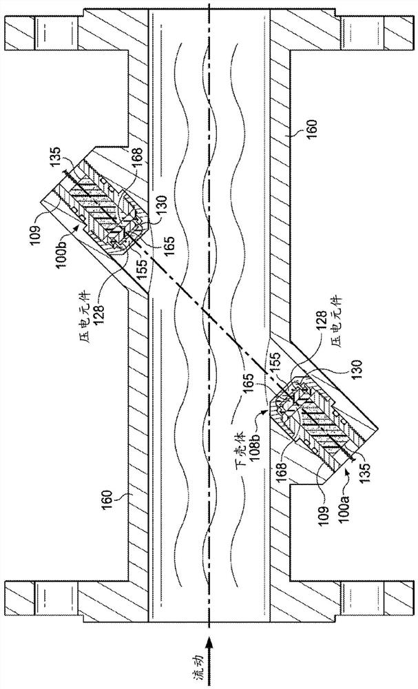
An ultrasonic flow meter (100) includes a housing (108) for attaching to a fluid pipe (160). A first piezoelectric element (128) coupled to a transmitter (Tx 111) and receiver (Rx 112) is configured to emit ultrasonic waves in an axial direction perpendicular to a horizontal plane defined by the piezoelectric element. A lens combination is in a lower housing portion (108b) positioned radially outside the first piezoelectric element including a refocusing lens (130) that is ring-shaped configured for redirecting received radial ultrasonic waves to travel in an axial direction perpendicular to the horizontal plane and has a thickness profile configured to act as a matching layer for reducing multiple reflections within the lower housing portion. A second lens (140) that is disc-shaped below the refocusing lens is configured for redirecting the radial ultrasonic waves to travel in the axial direction.

Description

technical field [0001] Embodiments disclosed herein relate to ultrasonic flow meters. Background technique [0002] Ultrasonic meters (USMs), also known as ultrasonic flow meters (UFMs), are becoming more common for fluid flow metering because they are capable of measuring a wide range of different flow rates, cause minimal pressure drop, and have non-moving parts so that Provides less mechanical maintenance and better reliability. A key hardware component in a USM is a piezoelectric element comprising a piezoelectric crystal or piezoceramic. As known in physics, the piezoelectric effect is the ability of certain materials to generate an electrical charge in response to applied mechanical stress. [0003] For flow metering applications, two or more piezo-based transducers transmit and receive ultrasonic signals to and from fluid flowing in a tube through a fully or partially encapsulated housing. In industries such as oil and gas, challenges remain in achieving high ultra...

Claims


Application Information

Patent Timeline
IPC IPC(8): G01F1/66G01P5/24
CPCG01F1/662G01F1/667B06B1/0644G01F1/66G01P5/24
Inventor 赛斌罗冬
Owner HONEYWELL INT INC
Learn More