
Two-camera triangulation scanner with detachable coupling mechanism

a triangulation scanner and coupling mechanism technology, applied in the field of coordinate measuring machines, can solve the problems of limited capture, registration method, and relatively difficult use of measurement installations, and achieve the effect of reducing the cost of use, and reducing the cost of operation

Active Publication Date: 2016-10-27
FARO TECH INC
View PDF38 Cites 69 Cited by
  • Summary
  • Abstract
  • Description
  • Claims
  • Application Information

AI Technical Summary

Benefits of technology

This patent describes a device for measuring the 3D coordinates of an object surface. The device includes a processor and a triangulation scanner consisting of a projector, first and second scanner cameras, and a scanner connector that can be attached to an articulated arm coordinate measurement machine (AACMM). The projector projects a pattern onto the surface and the first and second cameras capture images of the pattern. The processor uses the images to determine the 3D coordinates of the surface. The device can be used whether it is attached or unattached to the AACMM, and can easily be placed flat on its bottom after detachment. The technical effects of this device include improved accuracy and ease of use for measuring 3D coordinates of object surfaces.

Problems solved by technology

Portable AACMMs represent a vast improvement over known stationary or fixed, cost-intensive and relatively difficult to use measurement installations, particularly in the amount of time it takes to perform dimensional measurements of relatively complex parts.
Usually, such handheld operation is limited to capturing a line of light or pattern of light in a single shot.
A difficulty with this registration method may arise when an object being scanned has relatively few features.
In addition, although it is possible to use an area scanner removed from an AACMM in a handheld mode, it has not generally been possible to use an LLP in a handheld mode as a collection of single lines.
A potential difficulty is that the collecting of multiple lines may not provide enough information to permit multiple line-scans to be fit together over a two-dimension surface area.

Method used


Image

  • Two-camera triangulation scanner with detachable coupling mechanism
  • Two-camera triangulation scanner with detachable coupling mechanism
  • Two-camera triangulation scanner with detachable coupling mechanism

Examples


Embodiment Construction

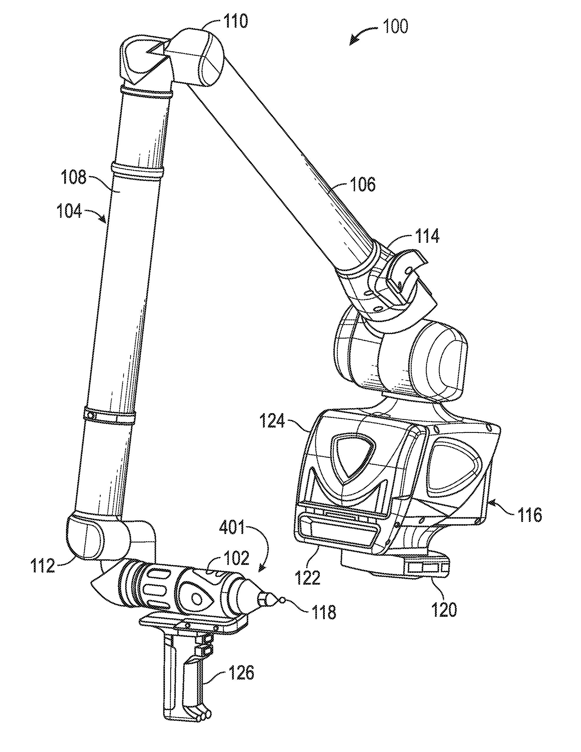
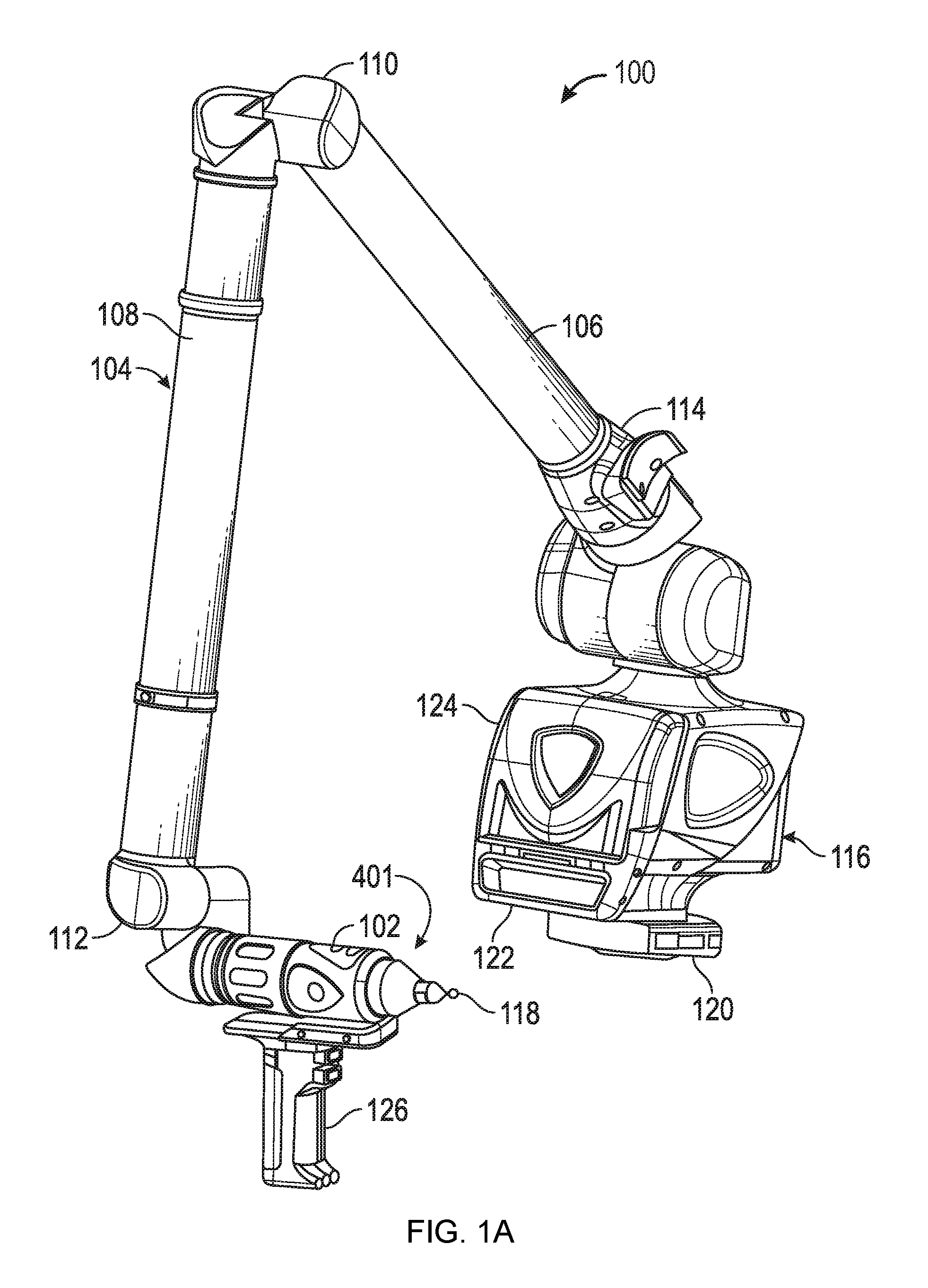
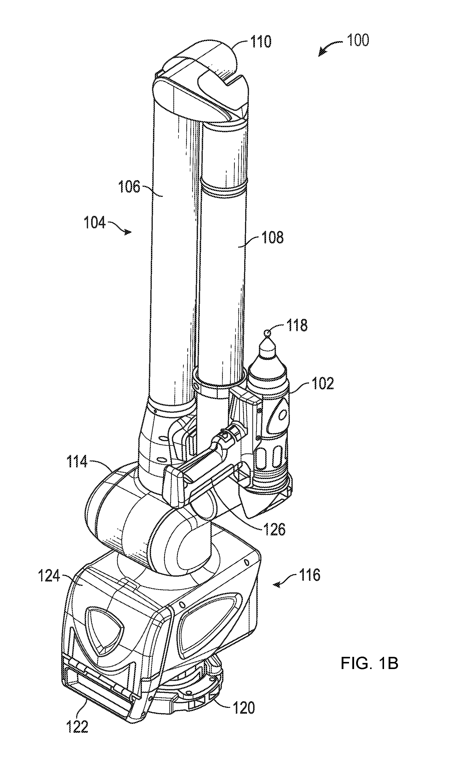
[0051]FIGS. 1A and 1B illustrate, in perspective, an articulated arm coordinate measuring machine 100 according to various embodiments of the present invention, an articulated arm being one type of coordinate measuring machine. As shown in FIGS. 1A and 1B, the exemplary AACMM 100 may comprise a six or seven axis articulated measurement device having a probe end 401 that includes a measurement probe housing 102 coupled to an arm portion 104 of the AACMM 100 at one end. The arm portion 104 comprises a first arm segment 106 coupled to a second arm segment 108 by a first grouping of bearing cartridges 110 (e.g., two bearing cartridges). A second grouping of bearing cartridges 112 (e.g., two bearing cartridges) couples the second arm segment 108 to the measurement probe housing 102. A third grouping of bearing cartridges 114 (e.g., three bearing cartridges) couples the first arm segment 106 to a base 116 located at the other end of the arm portion 104 of the AACMM 100. Each grouping of b...


PUM


Abstract

A three-dimensional (3D) scanner having two cameras and a projector is detachably coupled to a device selected from the group consisting of: an articulated arm coordinate measuring machine, a camera assembly, a six degree-of-freedom (six-DOF) tracker target assembly, and a six-DOF light point target assembly.

Description

CROSS REFERENCE TO RELATED APPLICATIONS[0001]This application claims the benefit of U.S. Provisional Patent Application No. 62 / 152,266 filed on Apr. 24, 2015, U.S. Provisional Patent Application No. 62 / 152,286, filed on Apr. 24, 2015, U.S. Provisional Patent Application No. 62 / 152,280, filed on Apr. 24, 2015, U.S. Provisional Patent Application No. 62 / 152,272, filed on Apr. 24, 2015, and U.S. Provisional Patent Application No. 62 / 152,294, filed on Apr. 24, 2015, the entire contents all of which are incorporated herein by reference.FIELD OF THE INVENTION[0002]The present disclosure relates to a coordinate measuring machine, and more particularly to a portable articulated arm coordinate measuring machine (AACMM) having a detachable accessory device.BACKGROUND OF THE INVENTION[0003]AACMMs have found widespread use in the manufacturing of parts where there is a need to rapidly and accurately verify the dimensions of the part during various stages of the manufacturing (e.g., machining) o...

Claims


Application Information

Patent Timeline
Patent Type & Authority Applications(United States)
IPC IPC(8): G01B11/25G06F3/041G01B11/00H04N13/02H04N13/239
CPCG01B11/2545H04N13/0239G01B11/2518G06F3/0412G01B11/005H04N13/0257G01B11/245G01B11/25H04N13/239H04N13/257H04N1/60
Inventor TOHME, YAZIDHEIDEMANN, ROLFGRAU, MARKUSBRIDGES, ROBERT E.
Owner FARO TECH INC
Learn More