
Locking manual drive unit for aircraft engine nacelle door operating system

a technology of nacelle door and operating system, which is applied in the direction of power plant inspection panel, wing accessories, gearing, etc., can solve the problems of mdus damage to the cowl, not allowing the specialized tool to remain in place, and the known mdus may suffer one or more drawbacks

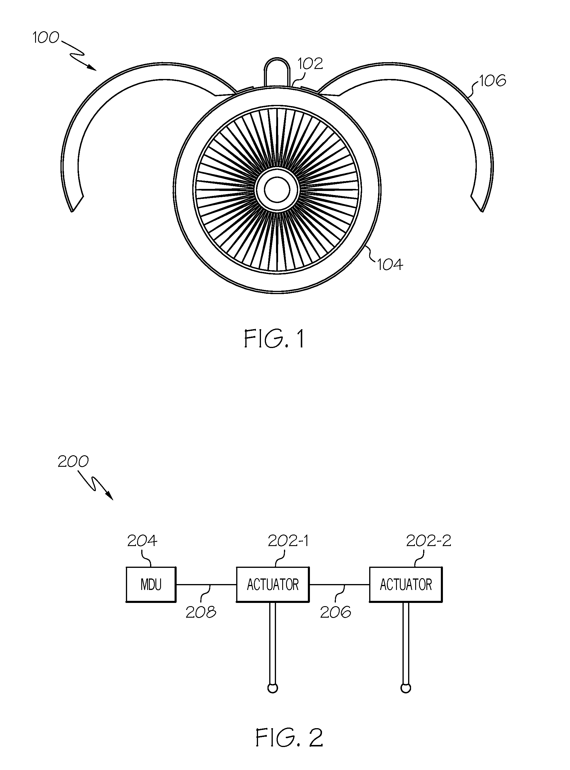
Active Publication Date: 2016-10-27
HONEYWELL INT INC
View PDF0 Cites 10 Cited by
  • Summary
  • Abstract
  • Description
  • Claims
  • Application Information

AI Technical Summary

Benefits of technology

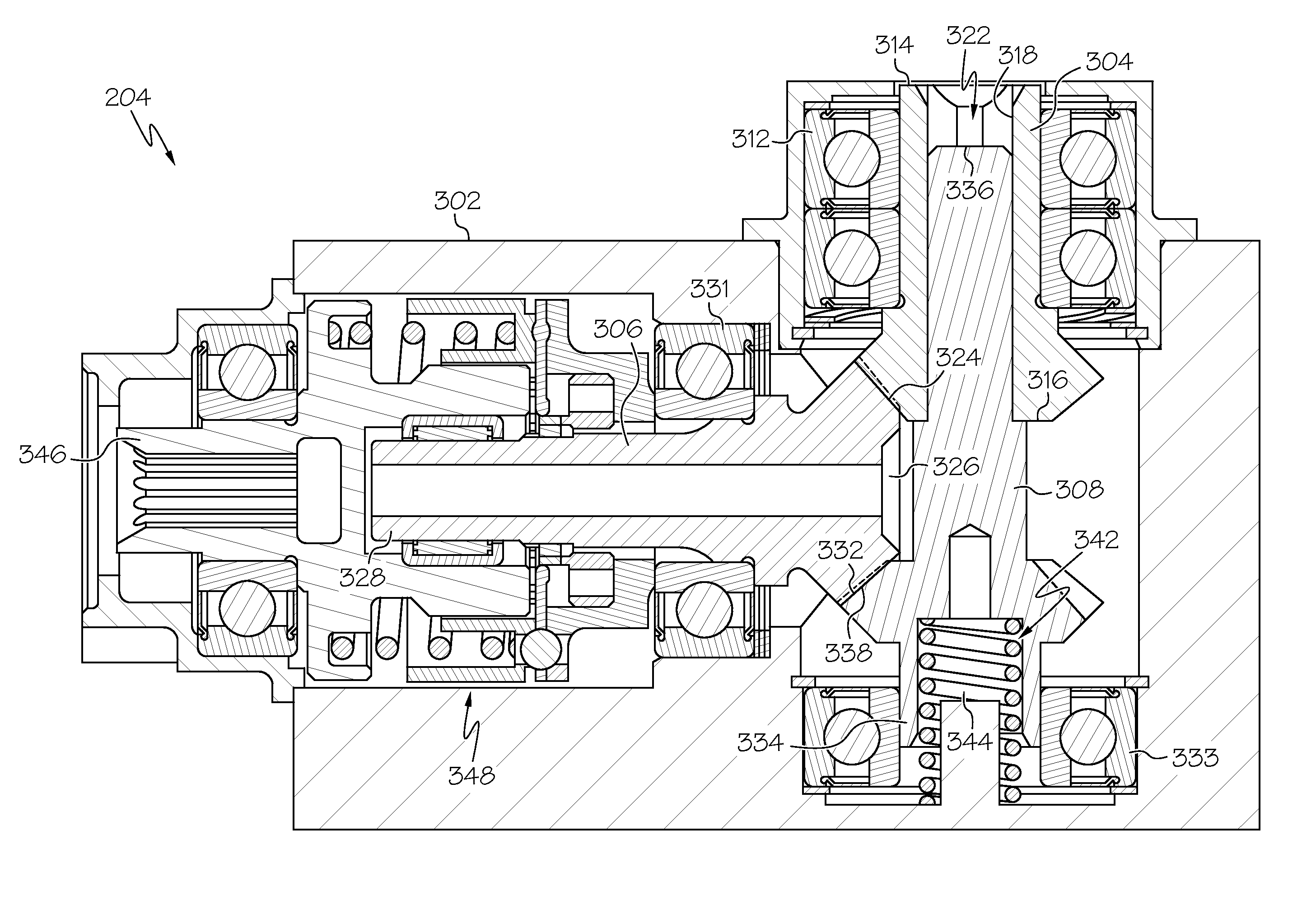
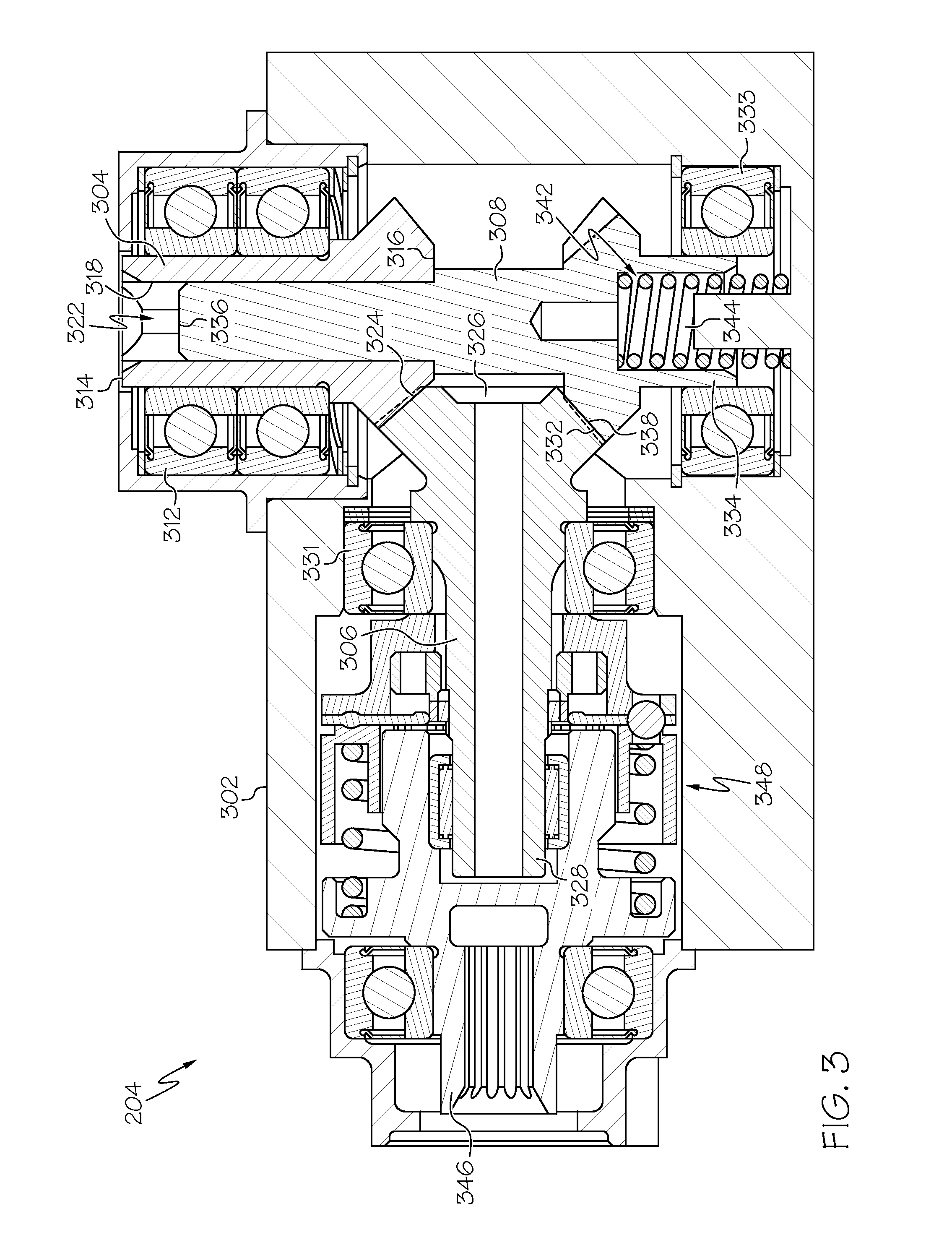
The patent describes a manual drive unit for aircraft engine nacelles and cowl doors. The unit includes a housing, input and output drive shafts, a lock shaft, and a lock spring. The input drive shaft is rotationally mounted in the housing and includes an inner surface with an input drive gear. The output drive shaft is rotationally mounted in the housing and includes an output drive gear that continuously engages and mates with the input drive gear. The lock shaft is rotationally mounted in the housing and extends at least partially into the axial bore and engages the inner surface of the input drive shaft. The lock spring is mounted in the housing and engages the housing and the lock shaft. The lock spring supplies a bias force to the lock shaft that urges the lock shaft toward the lock position. The manual drive unit allows for selective supply of drive torque to the actuator, which is coupled to the cowl door or engine nacelle, and can be easily operated to move the cowl door or engine nacelle.

Problems solved by technology

Although presently known MDUs are generally safe and reliable, these known MDUs may suffer one or more drawbacks.
For example, if an operator applies excessive manual drive force, known MDUs can damage the cowl when impacting stops at the stowed and deployed positions.
Hence, there is a need for a MDU that will not cause damage to the cowl when excessive drive force is applied and / or automatically engages the locking mechanism, and / or does not allow the specialized tool to remain in place after it is no longer needed.

Method used


Image

  • Locking manual drive unit for aircraft engine nacelle door operating system
  • Locking manual drive unit for aircraft engine nacelle door operating system
  • Locking manual drive unit for aircraft engine nacelle door operating system

Examples


Embodiment Construction

[0017]The following detailed description is merely exemplary in nature and is not intended to limit the invention or the application and uses of the invention. As used herein, the word “exemplary” means “serving as an example, instance, or illustration.” Thus, any embodiment described herein as “exemplary” is not necessarily to be construed as preferred or advantageous over other embodiments.

[0018]All of the embodiments described herein are exemplary embodiments provided to enable persons skilled in the art to make or use the invention and not to limit the scope of the invention which is defined by the claims. Furthermore, there is no intention to be bound by any expressed or implied theory presented in the preceding technical field, background, brief summary, or the following detailed description. Thus, although embodiments are, for convenience, described herein as being implemented in cowl door operating system, it will be appreciated that the described embodiments may be used in ...


PUM


Abstract

An aircraft engine nacelle door operating system locking manual drive unit includes a housing, an input drive shaft, an output drive shaft, a lock shaft, and a lock spring. The input drive shaft, the output drive shaft, and the lock shaft are all rotationally mounted in the housing. The output drive shaft continuously engages and mates with the input drive shaft, and he lock shaft extends at least partially into and engages the input drive shaft. The lock shaft is movable between a lock position, in which it engages and mates with the output drive shaft, and an unlock position, in it is disengaged from the output drive shaft. The lock spring supplies a bias force to the lock shaft that urges the lock shaft toward the lock position.

Description

CROSS REFERENCE TO RELATED APPLICATIONS[0001]This application claims the benefit of U.S. Provisional Application No. 62 / 152,467 filed Apr. 24, 2015.TECHNICAL FIELD[0002]The present invention generally relates to a manual drive unit, and more particularly relates to a locking manual drive unit for an aircraft engine nacelle door operating system.BACKGROUND[0003]The propulsion gas turbine engines installed on many aircraft are housed within a nacelle. Typically, the engine nacelle includes one or more cowl doors. The cowl doors may be moved between stowed (closed) and deployed (open) positions to allow maintenance personnel to access the interior of the nacelle to repair and maintain the engine.[0004]The movement of the cowl doors between the stowed and deployed positions may be accomplished via hydraulic, pneumatic, or electric actuation systems. There may be times, however, that the cowl doors need to be moved when hydraulic, pneumatic, or electric power is unavailable. In such inst...

Claims


Application Information

Patent Timeline
Patent Type & Authority Applications(United States)
IPC IPC(8): E05F11/02E05F15/00B64D29/08F16H1/20
CPCE05F11/02F16H1/203E05Y2900/502B64D29/08E05F15/00B64C1/1446B64D29/06F02K1/763F16H1/22F16H25/2454
Inventor CHAKKERA, KEVIN K.HARTMAN, TIMM E.VAUGHAN, RONBIRN, STEPHEN
Owner HONEYWELL INT INC
Learn More