
Torque modulation for internal combustion engine

Active Publication Date: 2016-10-20
JAGUAR LAND ROVER LTD
View PDF15 Cites 0 Cited by
  • Summary
  • Abstract
  • Description
  • Claims
  • Application Information

AI Technical Summary

Benefits of technology

[0021]varying the overlap of inlet and exhaust valves, by re-timing the opening of the inlet valve to increase or reduce overlap with operation of the exhaust valve. Reduced overlap will tend to increase the volume of air available for combustion, whereas increased overlap will tend to reduce the volume of air ava

Problems solved by technology

Output torque is reduced, but as a result combustion is relatively inefficient.
Inefficient combustion may also lead to an increase in undesirable exhaust emissions.
However it will be appreciated that the technique also relies upon inefficient combustion, with the disadvantages noted above.
It is also known to va

Method used


Image

  • Torque modulation for internal combustion engine
  • Torque modulation for internal combustion engine

Examples


Example

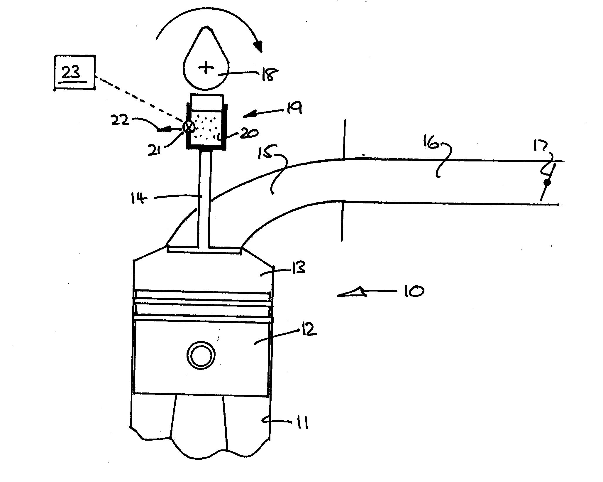
[0029]With reference to the drawings, an internal combustion engine 10 has a cylinder 11 within which a piston 12 reciprocates. A combustion chamber 13 is defined above the piston, and contains a poppet valve 14 which is opened to admit air from an inlet port 15. The inlet port is fed from an inlet manifold 16, at the mouth of which is provided a throttle valve 17.

[0030]The poppet valve 14 is closed by a spring (not shown), and is opened by action of a rotatable cam 18 which is conventionally provided by a lobe of a camshaft. Between the cam 18 and the valve 14 is provided a tappet 19.

[0031]The general arrangement of FIG. 1 is very common, and for ease of illustration certain other components, such as a corresponding poppet exhaust valve, are not illustrated. Conventionally the tappet 19 is solid, and may be characterized as passive.

[0032]The tappet of FIG. 1 is however active, and is characterized by a hydraulic chamber 20 whose volume is determined according to opening and closing...


PUM


Abstract

A method and apparatus for continually and rapidly adjusting the output torque of an engine according to a torque demand uses an active tappet to vary the instant air charge in a combustion chamber. The invention allows substantially efficient combustion throughout the engine operating map. Various methods of changing the charge of air are disclosed.

Description

TECHNICAL FIELD[0001]This invention relates to modulation of engine output torque in response to torque demand, and particularly to modulation of engine torque in a vehicle.BACKGROUND[0002]Historically modulation of engine output torque in a vehicle was solely by control of accelerator pedal position, which in turn usually determined the position of a throttle valve at the entrance to an air inlet manifold. The response of an engine to a change of throttle valve position is generally delayed by the volume of air in the inlet manifold (upstream of the inlet valve(s)), so that several combustion cycles may pass before output torque is modified in the intended direction. This delay is generally not noticed by vehicle drivers, or is accommodated by an alteration of driving style.[0003]More recently aspects of air management, fuel management and combustion timing have been under the control of an electronic control unit (ECU) of the engine, so that many kinds of operating conditions can ...

Claims


Application Information

Patent Timeline
IPC IPC(8): F02D13/02F01L9/02F02P5/04F01L13/00F02D41/26F02D37/02F01L1/14F01L9/14
CPCF02D13/0226F02D37/02F01L9/025F02D2250/18F01L13/0031F02D41/26F02P5/045F01L1/14F02D2041/001F02D2250/22F02D13/0223F01L2800/08F02D41/107F01L9/14F01L1/245F01L1/25F02D13/00F02D13/02F02D13/0203F01L13/0015F01L2013/118F02D13/023
Inventor BROCKLEY, NICK
Owner JAGUAR LAND ROVER LTD
Learn More