
System to prognose gas turbine remaining useful life

a gas turbine and prognose technology, applied in the field of flash thermography devices, can solve problems such as undesirable base metal overheating, clogging or blocking of cooling holes, and reducing engine efficiency

Active Publication Date: 2016-10-13
SIEMENS ENERGY INC
View PDF19 Cites 20 Cited by
  • Summary
  • Abstract
  • Description
  • Claims
  • Application Information

AI Technical Summary

Benefits of technology

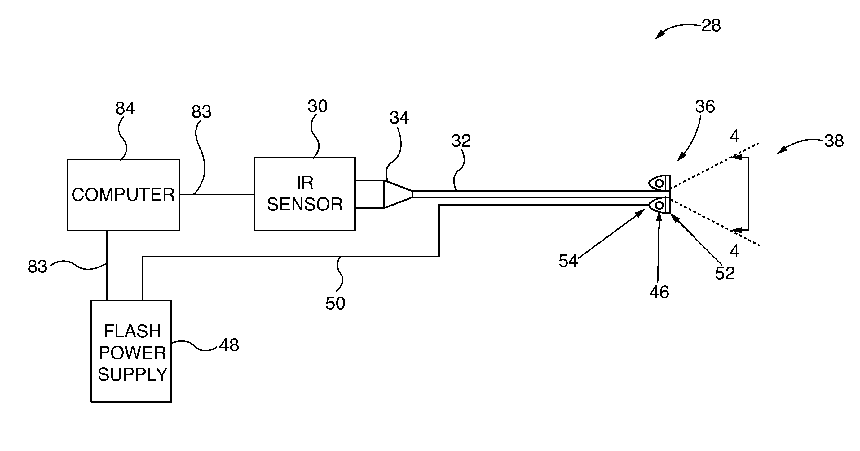
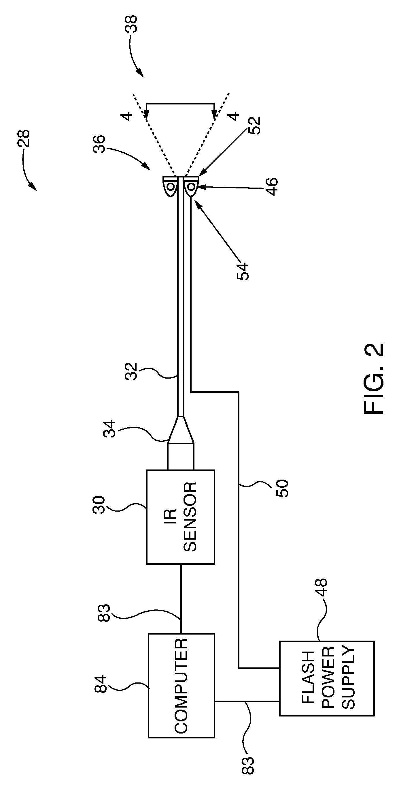
The patent describes a device and method for generating an infrared image of a turbine component located inside a turbine. The device includes a flash source and an infrared sensor, along with a borescope that is placed inside the turbine. The flash source heats the turbine component, and the infrared sensor detects the thermal energy that is radiated by the component. The borescope transmits the thermal energy to the infrared sensor, allowing an infrared image to be generated. The device does not need to remove or section the turbine component. The technical effect of this invention is the ability to inspect turbine components without the need for costly and time-consuming methods, thereby reducing downtime and improving efficiency.

Problems solved by technology

An increase in cooling effectiveness causes greater amounts of cooling air to be used in order to maintain a desired cooling capacity, which may cause a decrease in engine efficiency.
During operation of the turbine 10, the cooling holes may become clogged or blocked.
This compromises ability to cool an airfoil surface, which may lead to undesirable base metal overheating.
This also exposes the base metal to high temperatures, which may lead to oxidation of the base metal.
However, the current procedure is labor intensive, time consuming and expensive.

Method used


Image

  • System to prognose gas turbine remaining useful life
  • System to prognose gas turbine remaining useful life
  • System to prognose gas turbine remaining useful life

Examples


Embodiment Construction

[0019]Although various embodiments that incorporate the teachings of the present disclosure have been shown and described in detail herein, those skilled in the art can readily devise many other varied embodiments that still incorporate these teachings. The scope of the disclosure is not limited in its application to the exemplary embodiment details of construction and the arrangement of components set forth in the description or illustrated in the drawings. The disclosure encompasses other embodiments and of being practiced or of being carried out in various ways. Also, it is to be understood that the phraseology and terminology used herein is for the purpose of description and should not be regarded as limiting. The use of “including,”“comprising,” or “having” and variations thereof herein is meant to encompass the items listed thereafter and equivalents thereof as well as additional items. Unless specified or limited otherwise, the terms “mounted,”“connected,”“supported,” and “co...


PUM


Abstract

A flash thermography device for generating an infrared image of a turbine component located inside a turbine, wherein the turbine includes at least one inspection port. The device includes a flash source that generates a light pulse that heats the turbine component and an infrared sensor for detecting thermal energy radiated by the turbine component. The device also includes a borescope having a sensor end, a viewing end that includes the flash source and an interior hollow that extends between the sensor and viewing ends. The borescope is positioned in the inspection port such that the viewing end is located inside the turbine. Thermal energy radiated from the turbine component is transmitted through the hollow to the infrared sensor to enable generation of the infrared image. The device further includes a reflector located on the viewing end that directs the light pulse toward the turbine component and a flash power supply for energizing the flash source.

Description

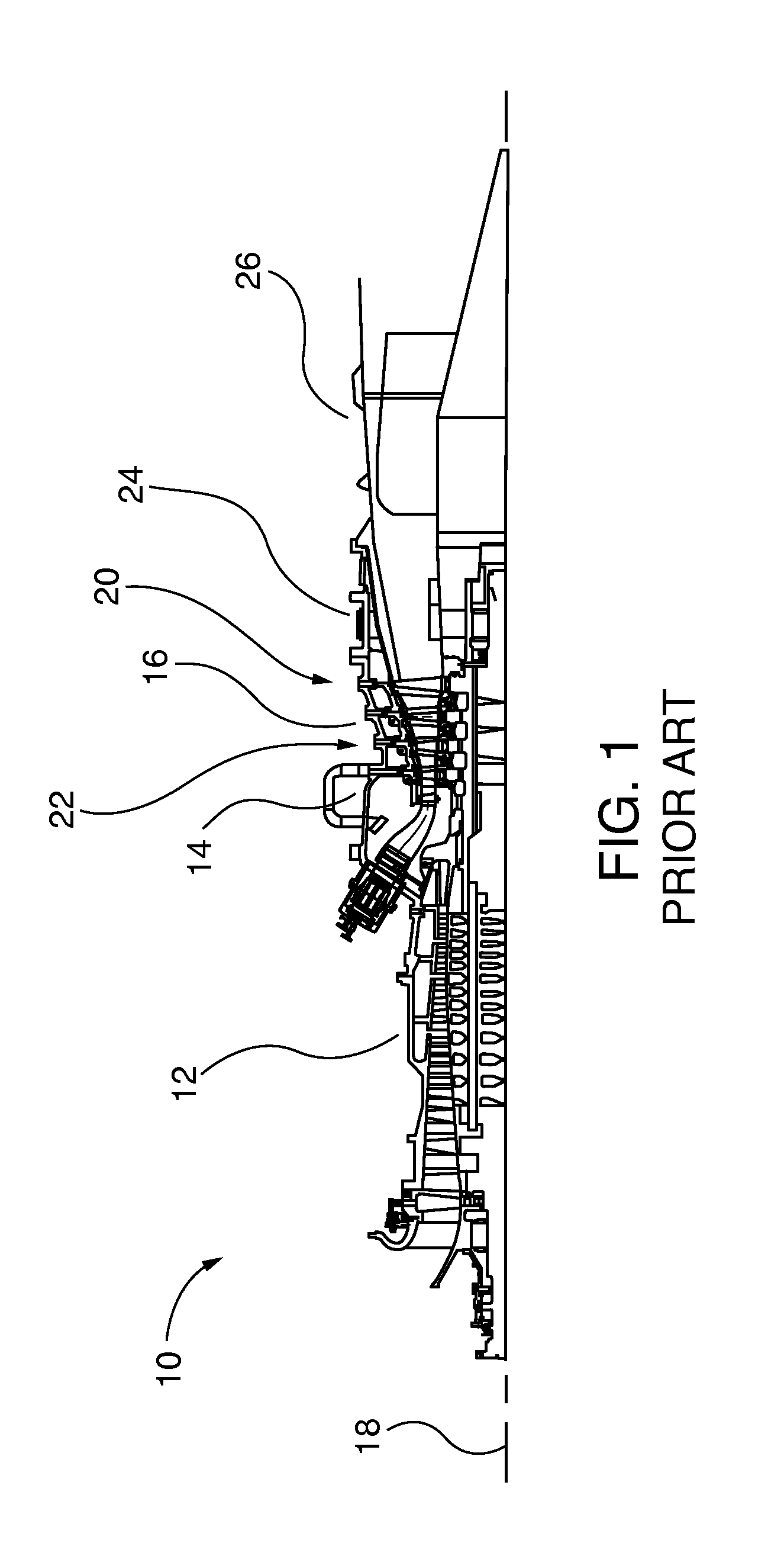
FIELD OF THE INVENTION[0001]This invention relates to flash thermography devices used in connection with turbines, and more particularly, to a flash thermography device that includes a borescope that is positioned in an inspection port of a turbine such that a viewing end of the device is delivered inside the turbine to enable generation of an infrared image of a hot gas path component located inside a turbine.BACKGROUND OF THE INVENTION[0002]In various multistage turbomachines used for energy conversion, such as gas turbines, a fluid is used to produce rotational motion. Referring to FIG. 1, an axial flow gas turbine 10 includes a compressor section 12, a combustion section 14 and a turbine section 16 arranged along a horizontal center axis 18. The compressor section 12 provides a compressed air flow to the combustion section 14 where the air is mixed with a fuel, such as natural gas, and ignited to create a hot working gas. The turbine section 16 includes a plurality of turbine bl...

Claims


Application Information

Patent Timeline
Patent Type & Authority Applications(United States)
IPC IPC(8): H04N5/33H04N7/18G02B23/24
CPCH04N5/33H04N7/183G02B23/2492F02C7/00F05D2260/80G02B23/2453G02B23/24G01J5/041G01J5/0896G01J5/0088G01J2005/0077G01J5/0818
Inventor IYER, ARUN MEENAKSHINATHAKULKARNI, ANAND A.LICATA, KEVIN
Owner SIEMENS ENERGY INC
Learn More