
Modular remote power generation and transmission for hydraulic fracturing system

Active Publication Date: 2016-10-06
US WELL SERVICS LLC
View PDF2 Cites 154 Cited by
  • Summary
  • Abstract
  • Description
  • Claims
  • Application Information

AI Technical Summary

Benefits of technology

The patent describes a hydraulic fracturing system that uses electric motors and pumps to fracture underground formations. The system includes a variable frequency drive to control the motor's speed and diagnostics to prevent motor damage. The system also includes a long distance source of electricity, transmission lines, and a transformer to connect the source to the motor. The system can have multiple motors that can be connected to the source of electricity at different times using moveable transmission lines. The technical effects of the patent are to improve the efficiency and reliability of hydraulic fracturing operations.

Problems solved by technology

The diesel engines and transmission which power hydraulic fracturing units typically generate large amounts of vibrations of both high and low frequencies.
These vibrations are generated by the diesel engine, the transmission, the hydraulic fracturing pump as well as the large cooling fan and radiator needed to cool the engine and transmission.
Low frequency vibrations and harshness are greatly increased by the large cooling fans and radiator required to cool the diesel engine and transmission.
Diesel powered hydraulic fracturing units are known to jack and jump while operating in the field from the large amounts of vibrations.
The vibrations may contribute to fatigue failures of many differed parts of a hydraulic fracturing unit.
Because of the high pressures generated by the pumps, and that the pumps used for pressurizing the fracturing fluid are reciprocating pumps, a significant amount of vibration is created when pressurizing the fracturing fluid.
The vibration transmits to the piping that carries the fracturing fluid and its associated equipment, thereby increasing probabilities of mechanical failure for the piping and equipment, and also shortening their useful operational time.

Method used


Image

  • Modular remote power generation and transmission for hydraulic fracturing system
  • Modular remote power generation and transmission for hydraulic fracturing system
  • Modular remote power generation and transmission for hydraulic fracturing system

Examples


Embodiment Construction

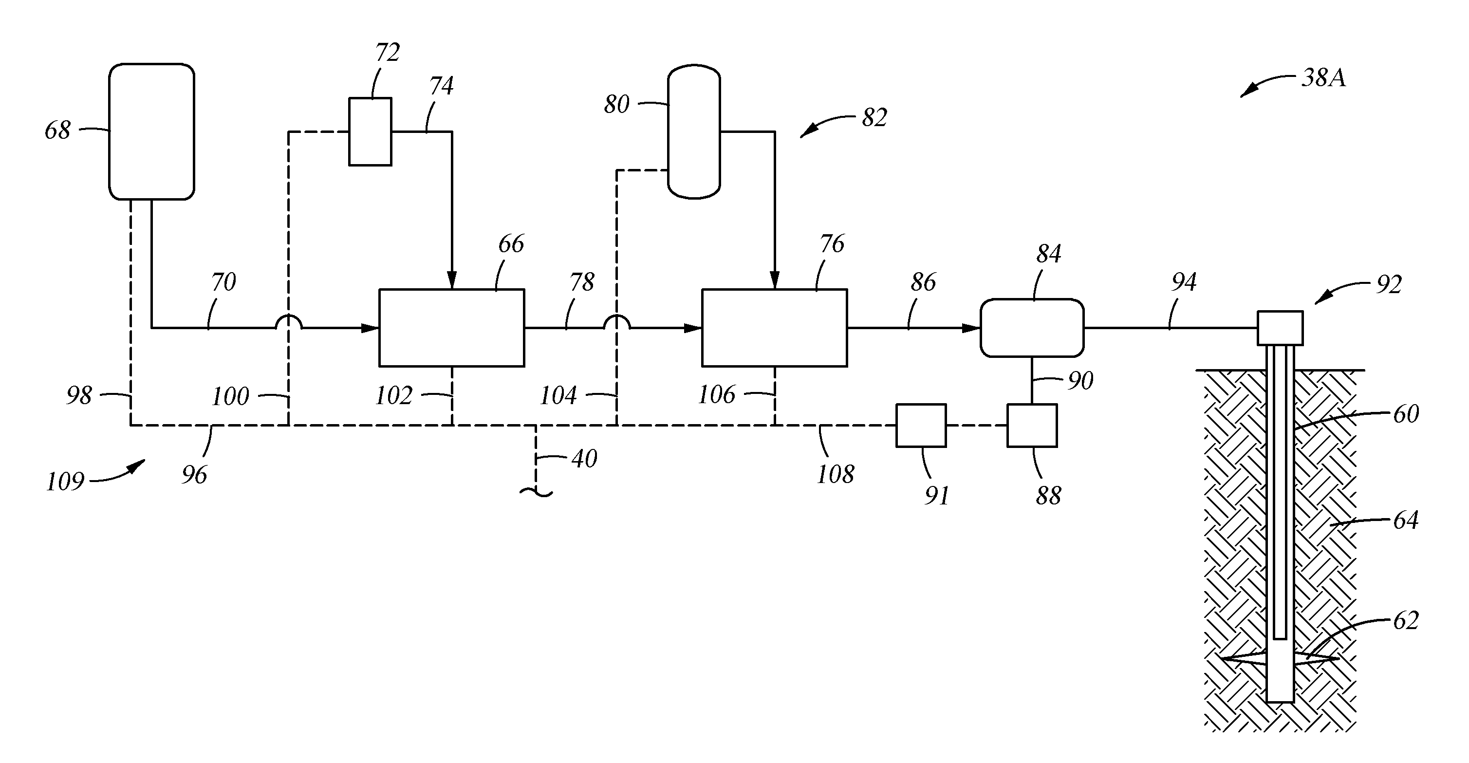
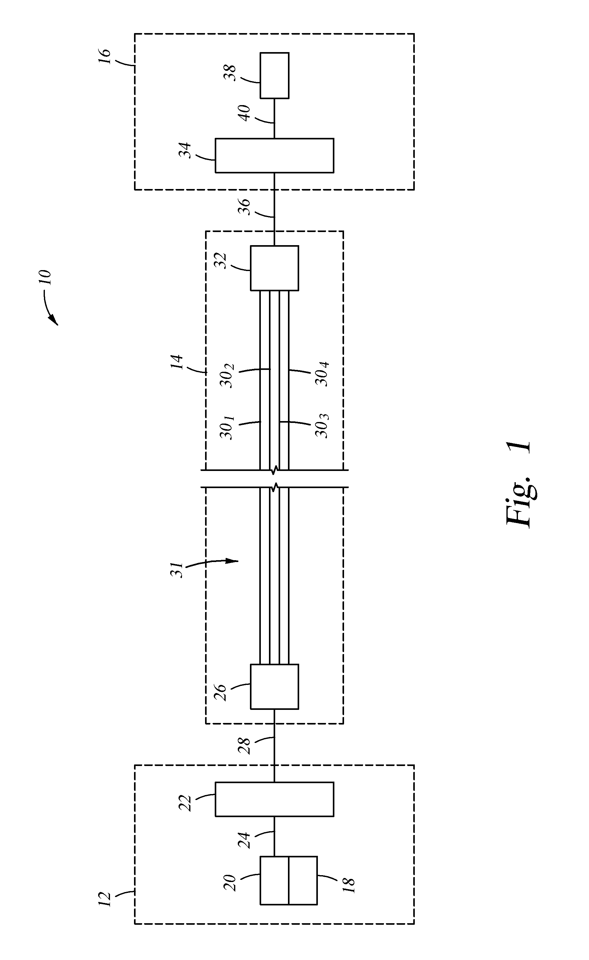
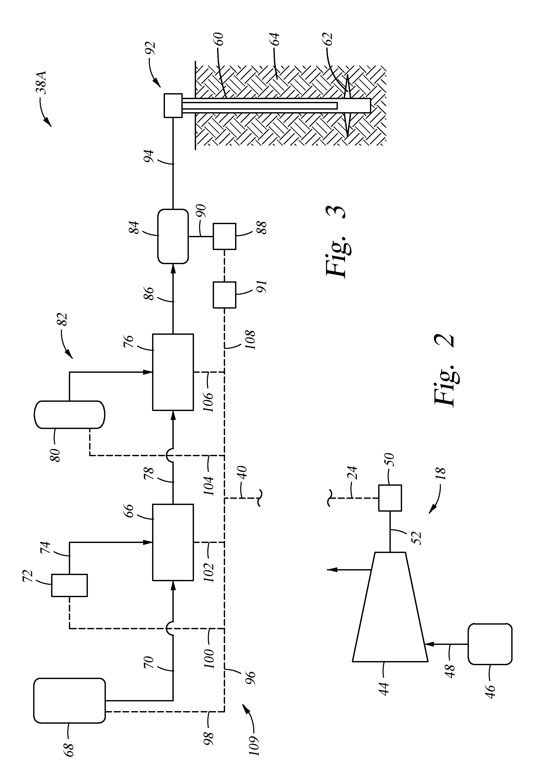
[0017]The method and system of the present disclosure will now be described more fully hereinafter with reference to the accompanying drawings in which embodiments are shown. The method and system of the present disclosure may be in many different forms and should not be construed as limited to the illustrated embodiments set forth herein; rather, these embodiments are provided so that this disclosure will be thorough and complete, and will fully convey its scope to those skilled in the art. Like numbers refer to like elements throughout. In an embodiment, usage of the term “about” includes + / −5% of the cited magnitude. In an embodiment, usage of the term “substantially” includes + / −5% of the cited magnitude.

[0018]It is to be further understood that the scope of the present disclosure is not limited to the exact details of construction, operation, exact materials, or embodiments shown and described, as modifications and equivalents will be apparent to one skilled in the art. In the ...


PUM


Abstract

A hydraulic fracturing system for fracturing a subterranean formation includes a power generation system, a transmission section, and an equipment load section. The power generation system includes a turbine generator that generates electricity that is used to power equipment in the equipment load section. The equipment in the equipment load section conditions and pressurizes fluid that is injected into a wellbore for fracturing the formation. The power generation and equipment load sections are distal from one another are separated by a long distance. The transmission section connects the power generation and equipment load sections, and thus spans the long distance between these sections.

Description

CROSS REFERENCE TO RELATED APPLICATIONS[0001]This application is a continuation of, and claims priority to and the benefit of, co-pending U.S. Provisional Application Ser. No. 62 / 180,140, filed Jun. 16, 2015 and is a continuation-in-part of, and claims priority to and the benefit of co-pending U.S. patent application Ser. No. 13 / 679,689, filed Nov. 16, 2012, the full disclosures of which are hereby incorporated by reference herein for all purposes.BACKGROUND OF THE INVENTION[0002]1. Field of Invention[0003]The present disclosure relates to hydraulic fracturing of subterranean formations. In particular, the present disclosure relates to a method and device for remotely generating and transmitting power for hydraulic fracturing of a subterranean formation.[0004]2. Description of Prior Art[0005]Hydraulic fracturing is a technique used to stimulate production from some hydrocarbon producing wells. The technique usually involves injecting fluid into a wellbore at a pressure sufficient to...

Claims


Application Information

Patent Timeline
IPC IPC(8): E21B43/26H02P29/02
CPCE21B43/26E21B43/267H02P29/02E21B43/2607
Inventor OEHRING, JAREDHINDERLITER, BRANDON NEIL
Owner US WELL SERVICS LLC
Learn More