
Fine-tuning speed application interface

a technology of application interface and fine tuning speed, which is applied in the direction of electrical programme control, program control, instruments, etc., can solve the problems of grinding or instability in machining operations, such as boring, turning, etc., and achieve the effect of reducing machine chatter and reducing machine chatter

Active Publication Date: 2016-10-06
DMG MORI CO LTD
View PDF10 Cites 12 Cited by
  • Summary
  • Abstract
  • Description
  • Claims
  • Application Information

AI Technical Summary

Benefits of technology

The present patent provides a method and computer-readable medium for reducing machine chatter during a cutting process. The method involves determining a speed for the machine, identifying a stability region based on the determined speed, and selecting a set of fine-tuning speeds from a range of machine speeds within the stability region. The machine is then operated at one or more of the fine-tuning speeds to reduce chattering. The technical effect of this patent is to improve the accuracy and efficiency of the cutting process by reducing machine chatter.

Problems solved by technology

As described for example in U.S. Pat. No. 5,170,358, which is incorporated herein by reference in its entirety, chatter or instability in machining operations, such as turning, boring, milling, and the like, is a common problem in industry.
Chatter is unwanted vibrations observed during the machining operation.

Method used


Image

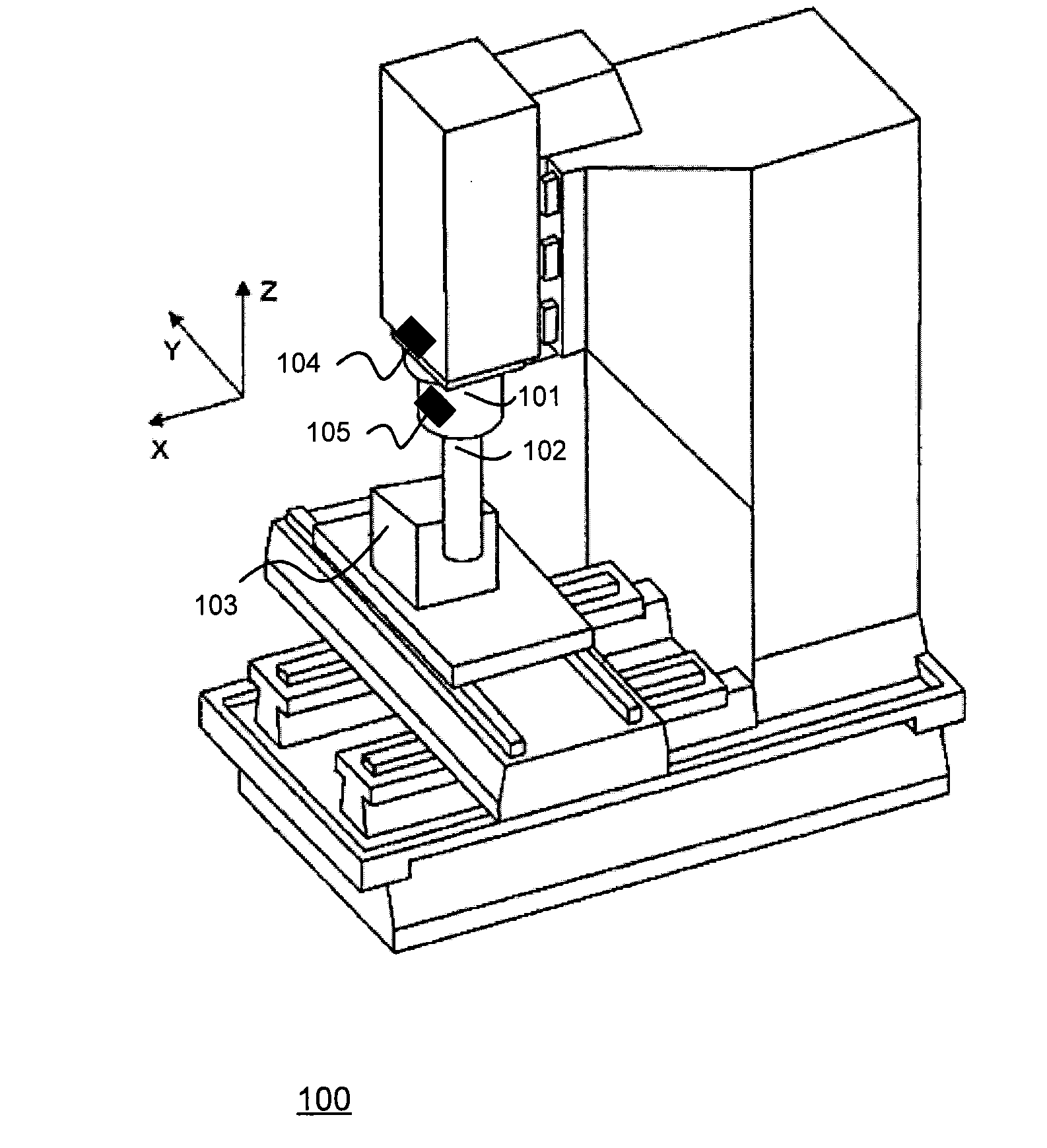
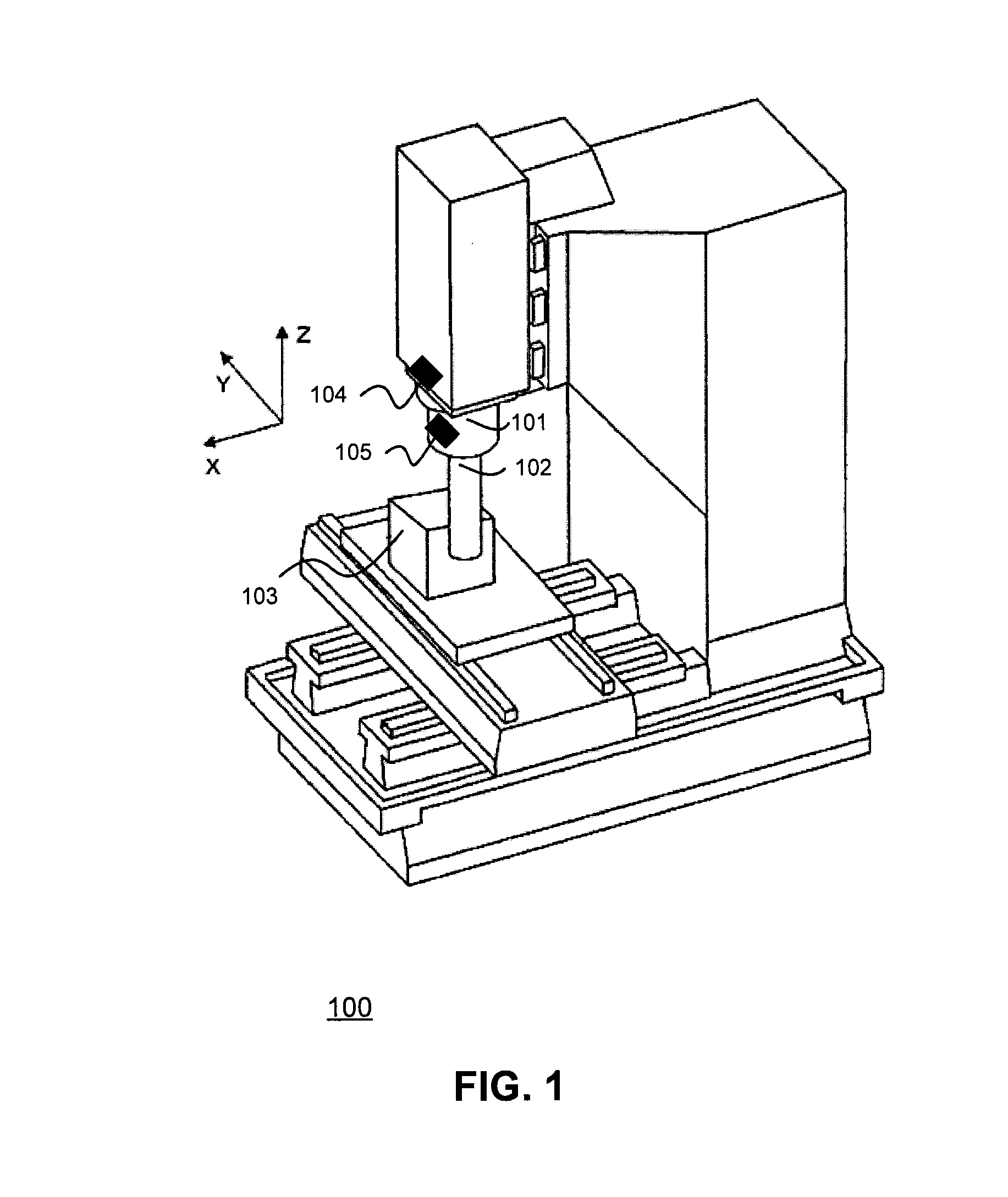
  • Fine-tuning speed application interface
  • Fine-tuning speed application interface
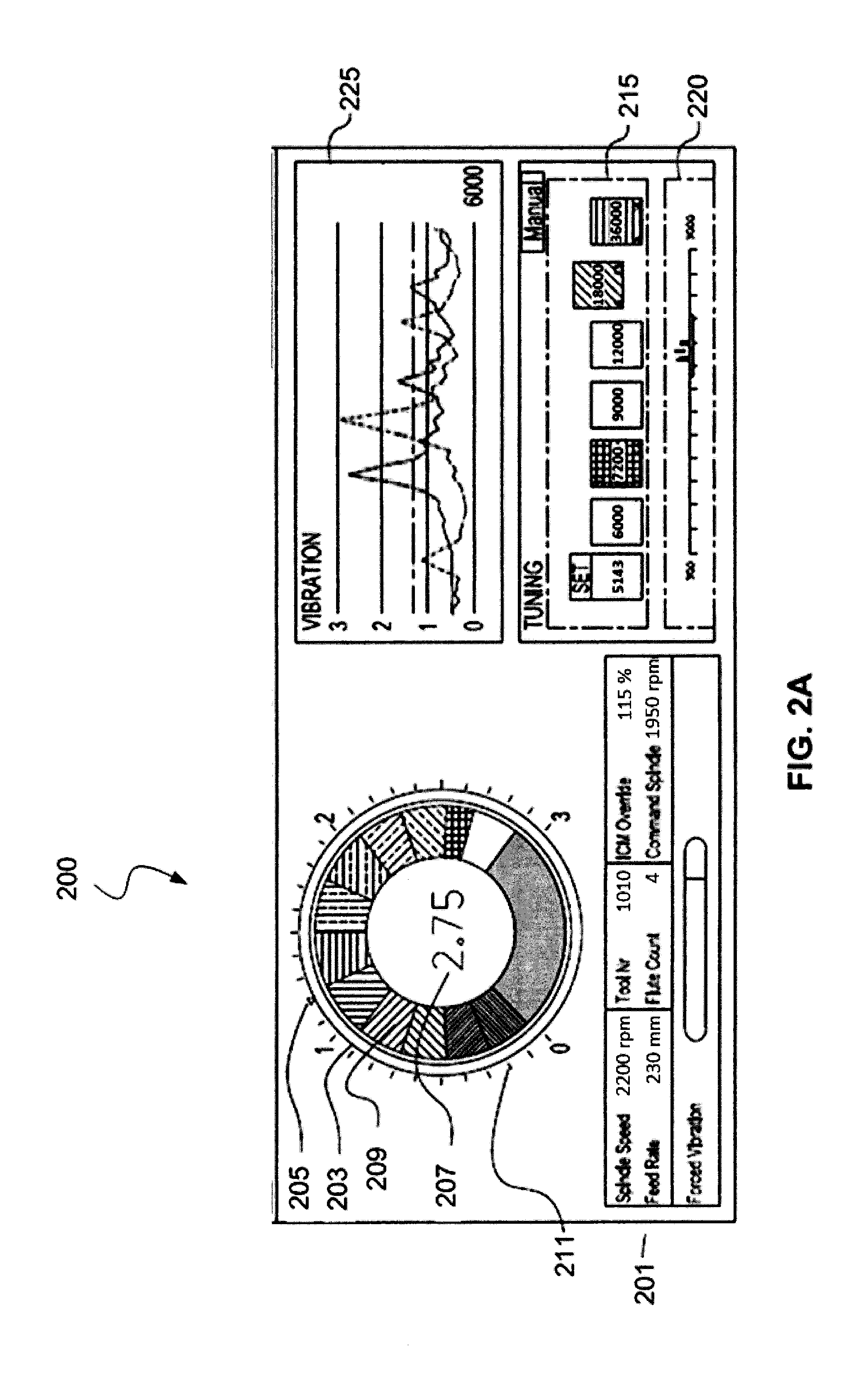
  • Fine-tuning speed application interface

Examples


Embodiment Construction

[0022]In the drawings, like reference numerals designate identical or corresponding parts throughout the several views. Further, as used herein, the words “a”, “an” and the like generally carry a meaning of “one or more”, unless stated otherwise. The drawings are generally drawn to scale unless specified otherwise or illustrating schematic structures or flowcharts.

[0023]Furthermore, the terms “approximately,”“proximate,”“minor,” and similar terms generally refer to ranges that include the identified value within a margin of 20%, 10%, or preferably 5% in certain embodiments, and any values therebetween.

[0024]The terms “speed”, “spindle speed”, “selected speed”, and similar terms refers to “tool rotation speed” or “work piece rotation speed” in revolutions per minute (rpm) unless specified otherwise. However, embodiments of the present disclosure are not so limited and it is understood that other units of speed may be utilized.

[0025]Vibrations generated during a machining operation ca...


PUM


Abstract

A system, method and computer-readable medium for fine-tuning speed selection for reducing machine chatter. The system includes circuitry configured to determine a predetermined speed of the machine. The circuitry identifies a stability lobe based on the predetermined speed of the machine and selects a first set of fine-tuning speeds from a range of machine speeds corresponding to the determined stability lobe. Further, the circuitry causes the machine to operate at one or more of the first set of fine-tuning speeds.

Description

BACKGROUND[0001]1. Field of the Disclosure[0002]This application relates to a system, method, computer-readable medium, and interface for reducing machine tool chatter.[0003]2. Description of the Related Art[0004]As described for example in U.S. Pat. No. 5,170,358, which is incorporated herein by reference in its entirety, chatter or instability in machining operations, such as turning, boring, milling, and the like, is a common problem in industry. Vibrations are primarily categorized into free, forced, and self-excited vibrations. Chatter is a type of self-excited vibration commonly observed during a machining operation (or process). Chatter can also be produced from forced vibrations under certain operating conditions.[0005]Chatter is unwanted vibrations observed during the machining operation. It can be caused by a detrimental vibration feedback loop through a machine tool, a work piece, and a machine. When occurring, vibrations from the feedback loop can often be attenuated by ...

Claims


Application Information

Patent Timeline
Patent Type & Authority Applications(United States)
IPC IPC(8): B23Q15/12G05B19/404
CPCB23Q15/12G05B2219/41256G05B19/404G05B19/416B23Q15/08B23Q17/0976B23Q17/12
Inventor PINER, ZACHARYDING, KENAMAZI, MEHDIKONISHI, KYLE
Owner DMG MORI CO LTD
Learn More