
Method of Operating a Security System with Deterrent Capability for Intimidation and Neutralization

a technology of intimidation and neutralization and security system, applied in the field of advanced security and/or surveillance system, can solve the problems of inability of existing surveillance system to provide real-time response against suspicious targets, inability of existing surveillance system to defend against or slow down suspicious targets,

Active Publication Date: 2016-09-29
NOVA PROD INC
View PDF3 Cites 3 Cited by
  • Summary
  • Abstract
  • Description
  • Claims
  • Application Information

AI Technical Summary

Benefits of technology

The present invention is a security system that uses advanced technology to deter or neutralize a suspicious target through the use of non-lethal deterrent and lethal means of neutralization. The system includes a control unit that communicates with multiple security cameras and entry doors, allowing for real-time response against the threatening target. The system utilizes deterrent capability to intimidate or neutralize a threatening target, providing a safer environment for both innocent people and law enforcement personnel. The system also includes a display screen and speaker module for displaying and emitting the video and audio data collected from the security cameras. The technical effects of the invention include improved surveillance and detection capabilities, as well as the ability to deter or neutralize a threatening target in real-time.

Problems solved by technology

Existing security / surveillance systems are limited to the detection and observance of an area to detect any potential intruders or assailants.
However, the existing surveillance systems is not able to provide any real time response against a suspicious target.
However, all of these existing surveillance systems are not able to defend against or slow down a suspicious target until the emergency personals arrive to the incident site.

Method used


Image

  • Method of Operating a Security System with Deterrent Capability for Intimidation and Neutralization
  • Method of Operating a Security System with Deterrent Capability for Intimidation and Neutralization
  • Method of Operating a Security System with Deterrent Capability for Intimidation and Neutralization

Examples


Embodiment Construction

[0013]All illustrations of the drawings are for the purpose of describing selected versions of the present invention and are not intended to limit the scope of the present invention.

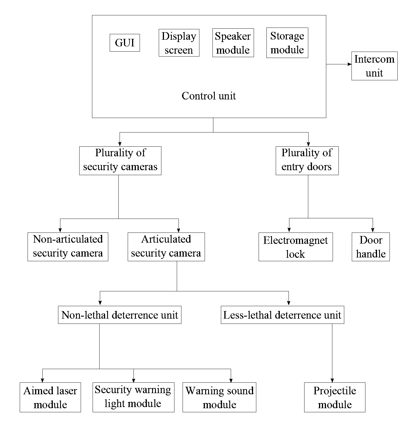
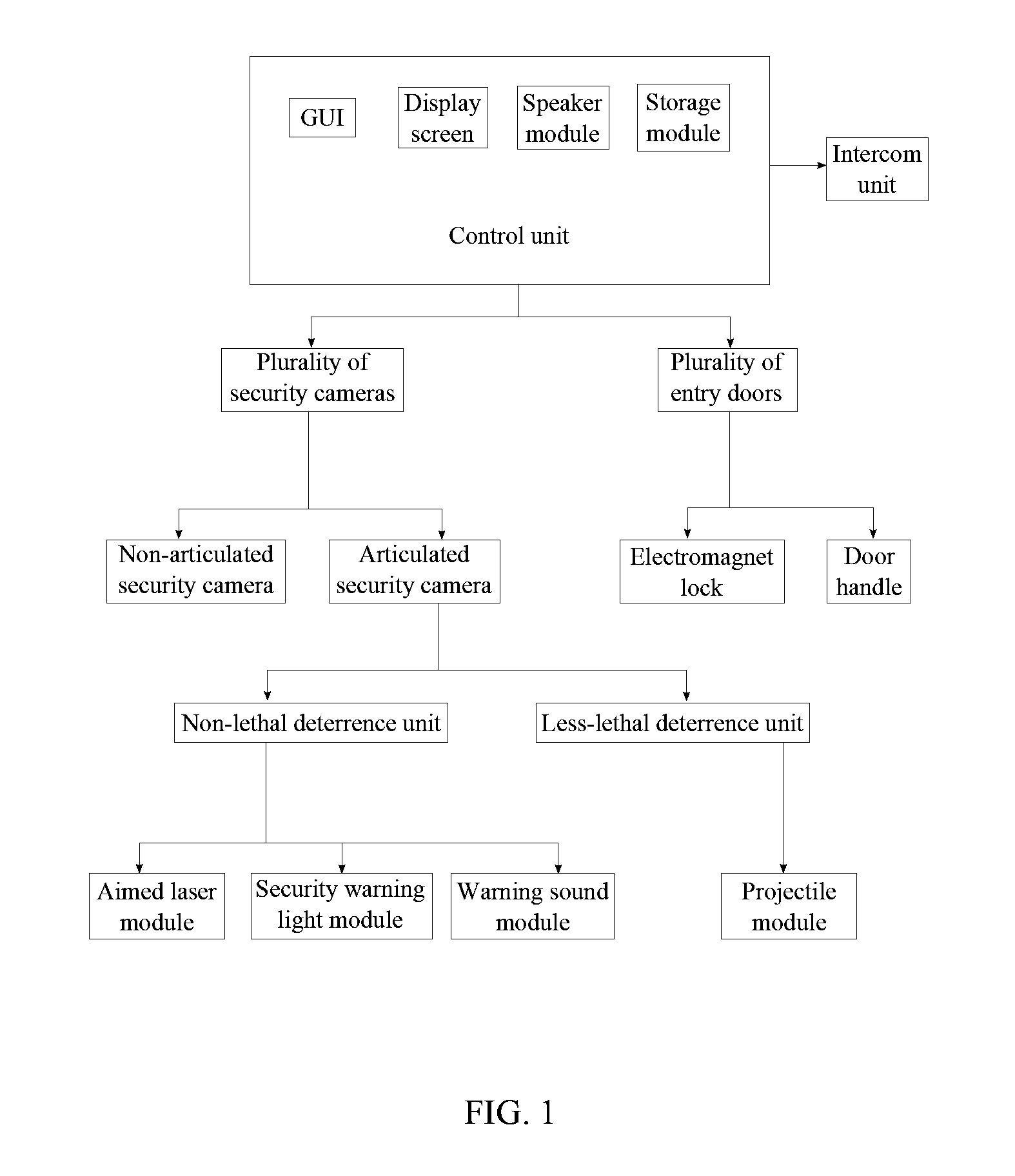
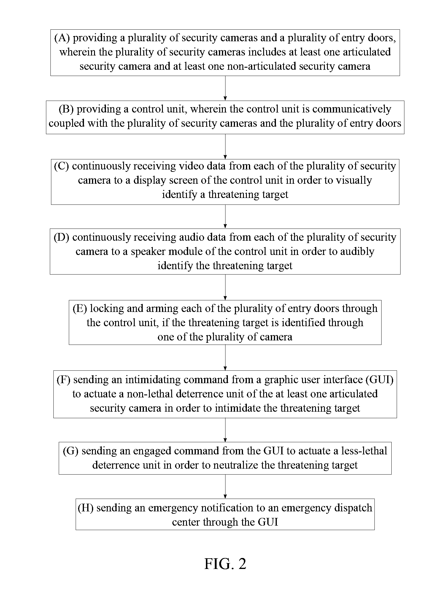
[0014]The present invention is a method of operating a security system that utilizes deterrent capability to intimidate or neutralize a threatening target. The deterrent capability of the present invention uses non-lethal forces and / or less-lethal force in order to successfully intimate or neutralize the threatening target. As a result, the present invention is able to defend against the threatening target while assuring the safety of the innocent people. The present invention is implemented through the security system that includes a plurality of security cameras, a plurality of entry doors, and a control unit. In reference to FIG. 1, the control unit is communicatively coupled with the plurality of entry doors and the plurality of security cameras that includes at least one articulated security camera ...


PUM


Abstract

A method of operating a security system with deterrent capability is implemented through security cameras that are articulated and non-articulated, entry doors, and a control unit. The control unit is communicatively coupled with the security cameras and the entry doors as the control unit is supervised by a trained operator. The security cameras continuously send audio and video data to the control unit so that a threatening target can be identified before he or she can do any destruction. When the threatening target is identified, the entry doors are locked and electrified through the control unit in order to provide an initial defense system for the threatening target. Additional deterrence can be implemented at the threatening target through a less-lethal deterrence unit and non-lethal deterrence units of the articulated security cameras while the non-articulated security cameras provide surveillance of the threatening target to the control unit.

Description

[0001]The current application claims a priority to the U.S. Provisional Patent application Ser. No. 62 / 023,037 filed on Jul. 10, 2014.FIELD OF THE INVENTION[0002]This invention is for an advanced security and / or surveillance system that provides capabilities to deter or neutralize a suspicious target through a non-lethal deterrence unit and a lethal deterrence unit in addition to the normal surveillance and detection capabilities seen in existing surveillance systems.BACKGROUND OF THE INVENTION[0003]Current security / surveillance systems observe a specific area primarily through the use of video displays that are connected to cameras that allow observance of the area using visible or infrared radiation. Existing security / surveillance systems are limited to the detection and observance of an area to detect any potential intruders or assailants. However, the existing surveillance systems is not able to provide any real time response against a suspicious target. For example, the existin...

Claims


Application Information

Patent Timeline
Patent Type & Authority Applications(United States)
IPC IPC(8): G08B13/196G08B15/00E05B1/00F42B12/46E05B47/00F41H13/00
CPCG08B13/19682E05B47/00G08B15/005E05B1/0007F42B12/46F41H13/0018G08B15/00
Inventor HAVENS, DAPHNE KAY
Owner NOVA PROD INC
Learn More