
System and Method of Control and Monitoring Access to a Restricted Area

Active Publication Date: 2016-09-29
DIGICON S A CONTROLE ELECTRONICSO PARA MECANICA
View PDF0 Cites 27 Cited by
  • Summary
  • Abstract
  • Description
  • Claims
  • Application Information

AI Technical Summary

Benefits of technology

The invention is a system and method for controlling and monitoring access to a restricted area. It allows authorized and special users to enter the area while identifying unauthorized or special users. This is achieved through the use of indicative windows with specific colors for each user category, which are placed at the barriers surrounding the area. The windows follow the user's movement, making it easier for security officers to identify unauthorized or special users and separate them from the rest of the audience. Overall, the invention improves the efficiency and accuracy of security measures in restricted areas.

Problems solved by technology

If the passage is not validated, the turnstile mechanism blocks the rotation of the arms thereby impeding the passage of an Unauthorized User.
However, in some circumstances, security personnel cannot quickly and accurately identify the unauthorized user.
However, these state of the art systems do not visually follow the user(s) movement within a gated area (i.e. the movement between the authentication device and the blocking device), so it is not possible to precisely identify the unauthorized user(s) who is (are) within the gated area.
Furthermore, state of the art access control systems identify the user's category only at the authentication device, so that authorized users with a special condition (such as, but not limited to, senior citizens, handicapped users, users exempt from payment, students, users with different fare conditions, visitors, third party workers, service providers, amongst others) are not precisely identified as they move within the Gated Area, resulting in attendance delays by security personnel, slow downs in the flow, and sometimes stoppage of flow at the blocking device.

Method used


Image

  • System and Method of Control and Monitoring Access to a Restricted Area
  • System and Method of Control and Monitoring Access to a Restricted Area
  • System and Method of Control and Monitoring Access to a Restricted Area

Examples


Embodiment Construction

[0030]For the purposes of this invention, the following terms are conceptualized:

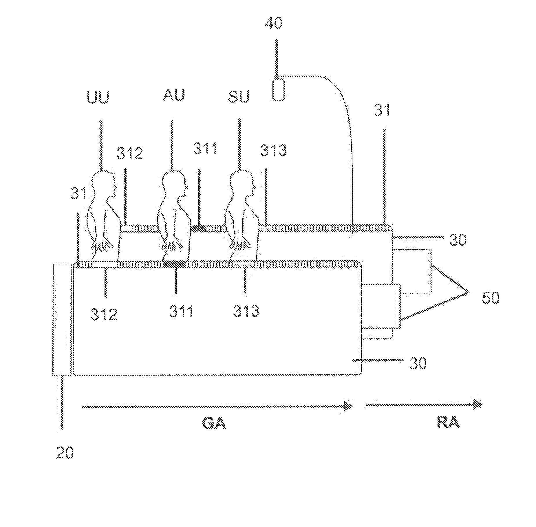
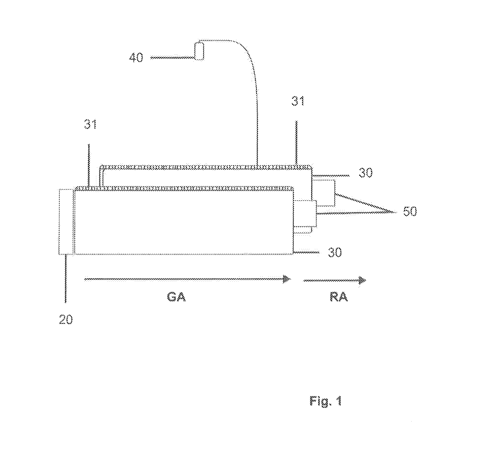
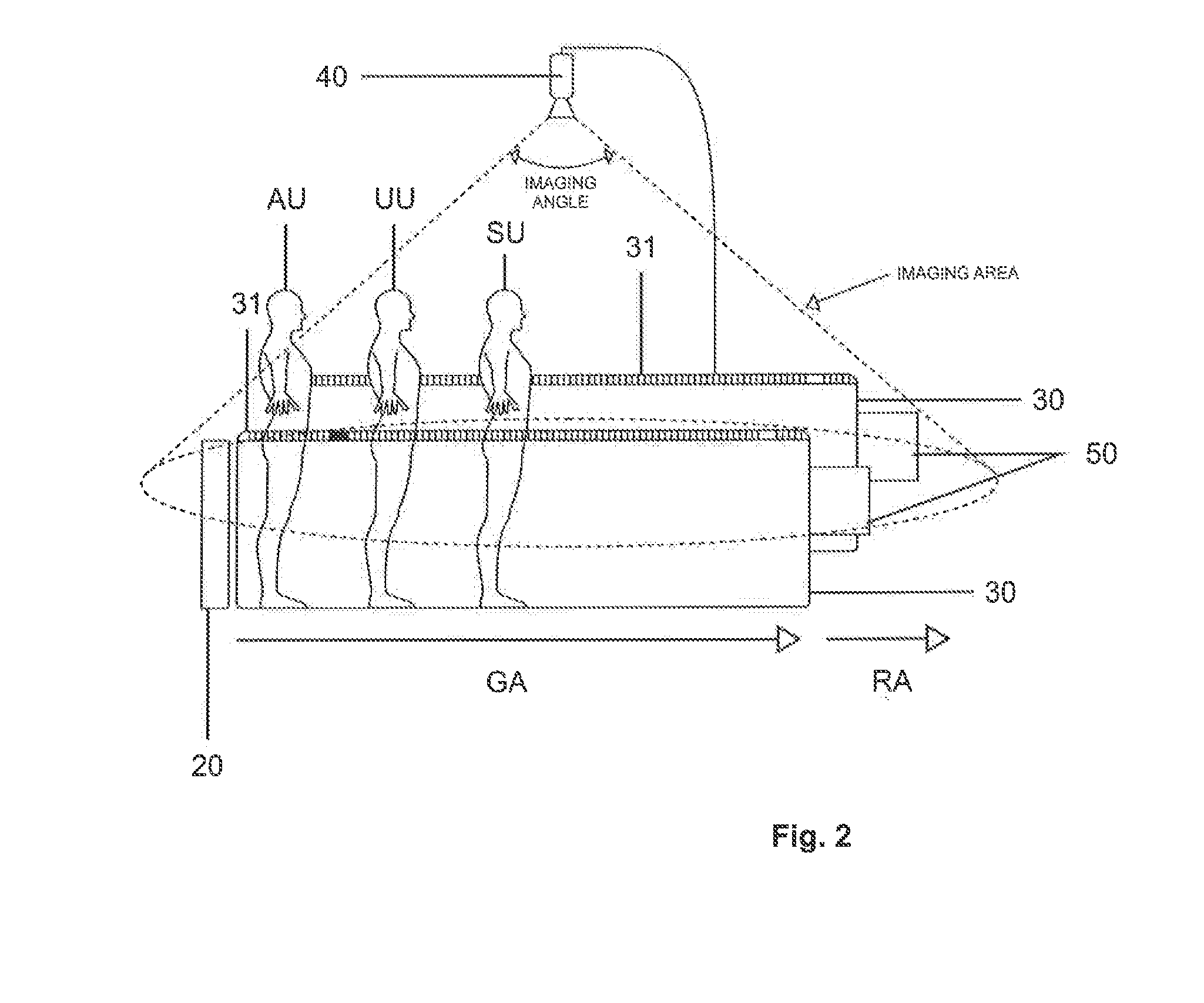
[0031]“Gated Area” (GA) is and area laterally bounded by Barriers (30) each equipped with a Bar of Luminous Elements (31). This Gated Area (GA) is positioned just before a Restricted Area (RA).

[0032]“Restricted Area” (RA) comprises an area for access only to Authorized Users (AU) and Special User (SU) previously enrolled in an User Authentication Device (20) located at the entrance of the Gated Area (GA). A Blocking Device (50) can be positioned immediately before the Restricted Area (RA) which allows entry to the Restricted Area (RA) by Authorized Users (AU) and / or Special Users (SU) and prevents access to the Restricted Area (RA) by Unauthorized Users (UU).

[0033]“Authorized User” (AU) comprises the user category that is authorized for entry into the Restricted Area (RA). Authorization is given by the User Authentication Device (20), usually located at the entrance of the Gated Area (GA).

[0034]“Special...


PUM


Abstract

We describe a control and monitoring system and method for access to a restricted area, such as mass transport systems (subways, trains, airports, ships and others), commercial buildings, schools, factories, datacenters, and other places with people moving, composed of a Processing Unit (10) that receives information both from a User Authentication Device (20) and an Image Capture Device (40). The Processing Unit (10) processes this information determining user category as well as user location, speed and direction of movement within a Gated Area (GA). In turn, the Processing Unit (10) triggers one or more Bars of Luminous Elements (31) arranged in Barriers (30) limiting a Gated Area (GA), giving every user (Authorized User [AU], Unauthorized User [UU] or Special User [SU]) a User Category Window (311, 312 or 313) that follows the movement of the user within the Gated Area (GA). A Blocking Device (50) can be activated by the Processing Unit (10) to be partially or fully closed or opened and at a speed proportional to the location, velocity and direction of movement of the user within the Gated Area (GA).

Description

FIELD OF THIS INVENTION[0001]This invention describes a control and monitoring system and method for access to a restricted area, such as mass transit systems (metro stations, train stations, airports, ports and others), commercial buildings, schools, factories, data centers and other places where the movement of people into restricted areas must be controlled. It more specifically comprises a monitoring and access control system with a processing unit which receives information from a user authentication unit and an image capture device and in turn activates one or more bars of luminous elements arranged in barriers which limit a Gated Area. Each user category (Authorized User, Unauthorized User or Special User) is associated with an indicative window of a specific and programmed color that accompanies the movement of the user within the Gated Area, facilitating the action of security agents with regard to visual identification and eventual approach to an Unauthorized User and perm...

Claims


Application Information

Patent Timeline
IPC IPC(8): G07C9/00G01B17/00G01B15/00E06B11/08G01B11/14G07C9/20
CPCG07C9/00071E06B11/08G01B17/00G01B15/00G01B11/14G07C9/15G07C9/37G07C9/32G01B11/002G07C9/00G07C9/10G07C9/25
Inventor ELBLING, PETER RICHARDARAND, MARIO
Owner DIGICON S A CONTROLE ELECTRONICSO PARA MECANICA
Learn More