Roll manufacturing method and manufacturing device

a manufacturing method and roll technology, applied in the direction of thin material handling, transportation and packaging, article delivery, etc., can solve the problems of reducing yield, limiting productivity, and increasing transportation difficulties, so as to prevent the possibility of web defects, improve the transportation quality of the web, and reliably perform a plurality of web operations

Active Publication Date: 2016-09-29
SAMSUNG CORNING PRECISION MATERIALS CO LTD
View PDF8 Cites 3 Cited by
  • Summary
  • Abstract
  • Description
  • Claims
  • Application Information

AI Technical Summary

Benefits of technology

This patent describes a method and apparatus for preventing defects and improving the quality of transporting a web through ultrasonic vibrations. By using a vibration suppressing unit that includes two ultrasonic vibrators, the method includes shaping the web, transporting it, suppressing vibrations, and winding it into a roll. This prevents the web from coming into contact with the surface of equipment and allows for better transportation quality based on the reliable floating force of ultrasonic waves. The invention also enables multiple operations to be performed on the web, including processing, examination, measurement, control, and transportation, while preventing defects from occurring in the web.

Problems solved by technology

At a substrate thickness of 0.3 mm or less, difficulties in transportation become higher, as compared to existing sheet types.
This consequently decreases yield and limits productivity.
However, in the glass substrate industry to which the present invention relates, the surface quality of a glass substrate is an important factor, and the quality of a product may be adversely influenced by surface scratches, contaminants or substrate damage that could result from the contact transportation.
However, this approach requires separate equipment to be added, making the process complicated and increasing equipment costs.
In addition, the additional attached or applied material is continuously consumed, contributing to an increase in the price of products.
However, the air floatation scheme may cause problems when applied to the transportation of a thin glass web.
In addition, the thin glass web is a brittle material that easily breaks.
For example, the air floatation has difficulties in terms of control of a flow of fluid and is influenced by turbulence, thereby resulting in the transportation of the glass web being unstable.
In addition, when air is contaminated, the surface of the glass web may also be contaminated, leading to an adverse effect on the quality of a resultant product.
Furthermore, since a predetermined pressure of filtered air must be continuously fed, a significant utility cost is caused, thereby increasing manufacturing costs.
In addition, if the process is elongated, the connection of pipes for supplying the floating air becomes more complicated, thereby increasing initial equipment investment costs.
In some cases, the web may vibrate undesirably through resonance.
Such vibrations of the web not only generate noise, but also become a factor in lowering and degrading several types of processing precision.
Such vibrations also cause adverse effects not only on the operation of processing the web, but also on the precision of the operations of examining, measuring, controlling, or transporting the web.
However, according to this method, it is critically difficult to uniformly adjust the height of the web using only the rate of air flow, and the force maintaining the web in a non-contact state is very weak.

Method used


Image

  • Roll manufacturing method and manufacturing device
  • Roll manufacturing method and manufacturing device
  • Roll manufacturing method and manufacturing device

Examples


Embodiment Construction

[0025]Reference will now be made in detail to embodiments of the present invention in conjunction with the accompanying drawings and described below, so that a person skilled in the art to which the present invention relates could easily put the present invention into practice.

[0026]Throughout this document, reference should be made to the drawings, in which the same reference numerals and signs are used throughout the different drawings to designate the same or similar components. In the following description of the present invention, detailed descriptions of known functions and components incorporated herein will be omitted in the case that the subject matter of the present invention is rendered unclear.

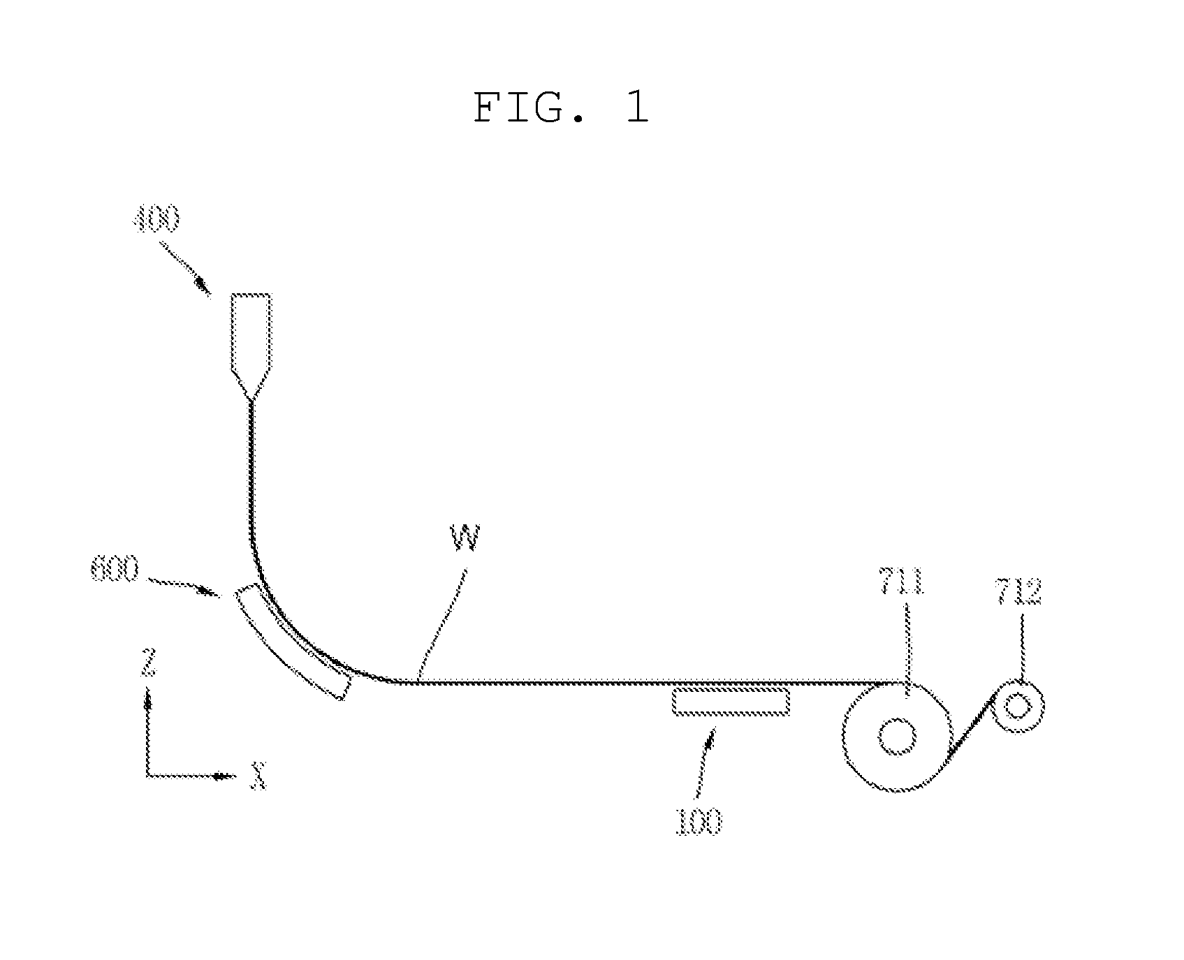
[0027]FIG. 1 is a schematic side-elevation view illustrating a first exemplary embodiment of an apparatus for manufacturing a roll according to the invention.

[0028]The apparatus for manufacturing a roll illustrated in FIG. 1 includes a shaping unit 400, a transportation unit 100, a...


PUM

PropertyMeasurementUnit
thicknessaaaaaaaaaa
thicknessaaaaaaaaaa
thicknessaaaaaaaaaa

Abstract

The present invention provides a roll manufacturing method characterized by comprising: a shaping step of shaping a base material into a web; a transferring step of transferring the shaped web; and a winding step of winding the transferred web into a roll. In addition, the present invention provides a roll manufacturing device characterized by comprising: a shaping unit for shaping a base material into a web; a transferring unit for transferring the shaped web; and a winding unit for winding the transferred web into a roll.

Description

BACKGROUND OF THE INVENTION[0001]1. Field of the Invention[0002]The present invention relates to a method and apparatus for manufacturing a roll, and more particularly, to a method and apparatus for manufacturing a roll able to prevent a web from coming into contact with the surface of equipment through ultrasonic vibrations, thereby preventing the possibility of defects occurring in the web.[0003]2. Description of Related Art[0004]As display devices become thinner and lighter, glass substrates are also becoming thinner. Due to the continuing trend for thinner device profiles, the thickness of substrates has changed from the existing thickness of 0.7 mm to a currently-preferred thickness of 0.5 mm or less. At a substrate thickness of 0.3 mm or less, difficulties in transportation become higher, as compared to existing sheet types. This consequently decreases yield and limits productivity. Accordingly, an approach of applying a roll-to-roll process, a process that has commonly been u...

Claims


Application Information

Patent Timeline
Patent Type & Authority Applications(United States)
IPC IPC(8): B65H23/188B65H35/02
CPCB65H23/188B65H2801/61B65H2515/50B65H35/02B65H2301/441B65H26/00B65H18/00B65H35/04
Inventor KIM, KI NAMKIM, SHINSEOL, MUN HWANCHO, DONG YOUNG
Owner SAMSUNG CORNING PRECISION MATERIALS CO LTD
Why Eureka
Try Eureka