Tandem position control device

a position control and servo technology, applied in the direction of programme control, electric programme control, electric motor speed/torque regulation, etc., can solve the problems of deteriorating response characteristic, inability to execute torque compensation control, and inability of one control shaft side to simultaneously detect on a real time basis the velocity of its own shaft and that of the other shaft. achieve the effect of preferable damping characteristi

Active Publication Date: 2016-09-22
OKUMA CORP
View PDF8 Cites 7 Cited by
  • Summary
  • Abstract
  • Description
  • Claims
  • Application Information

AI Technical Summary

Benefits of technology

[0027]With the above, a torque command value including a deflection vibration reduction torque compensation amount added is obtained, and accordingly, it is possible to achieve tandem control with preferable damping characteristic and response characteristic with an appropriate attenuation coefficient ζ, depending on a target plant condition that varies significantly.
[0028]According to a position control device according to the present invention, it is possible to promptly achieve tandem control capable of torque compensation control with preferable attenuation characteristic at the time of shifting to the tandem control state even in a structure including independently formed first and second shaft position control units and incapable of torque compensation control using a deflection velocity between control shafts, or in the case where the independent control state and the tandem control state are repetitively switched and the target plant condition thus varies significantly.

Problems solved by technology

However, with Gd=70→Gd=200 set, damping characteristic becomes excessive, which deteriorates response characteristic.
However, according to a typical position control device, it is often a case that the first shaft position control unit and the second shaft position control unit are independently formed, and in such a structure, it is not possible on one control shaft side to simultaneously detect on a real time basis the velocity of its own shaft and that of the other shaft.
Therefore, it is not possible to execute torque compensation control using a deflection velocity between control shafts relative to a target plant in the tandem control state.
Therefore, even though the amplification rate Gd is selected in advance, the attenuation coefficient ζ resultantly deviates significantly from an appropriate value once the workpiece is changed to another, and accordingly it is not possible to achieve tandem control with preferable damping characteristic and response characteristic.

Method used


Image

  • Tandem position control device
  • Tandem position control device
  • Tandem position control device

Examples


Embodiment Construction

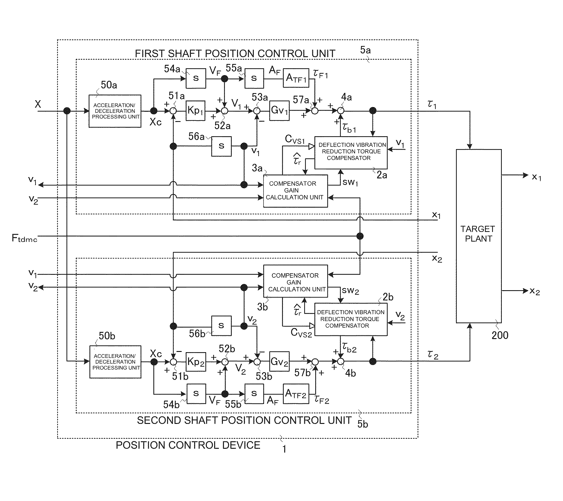
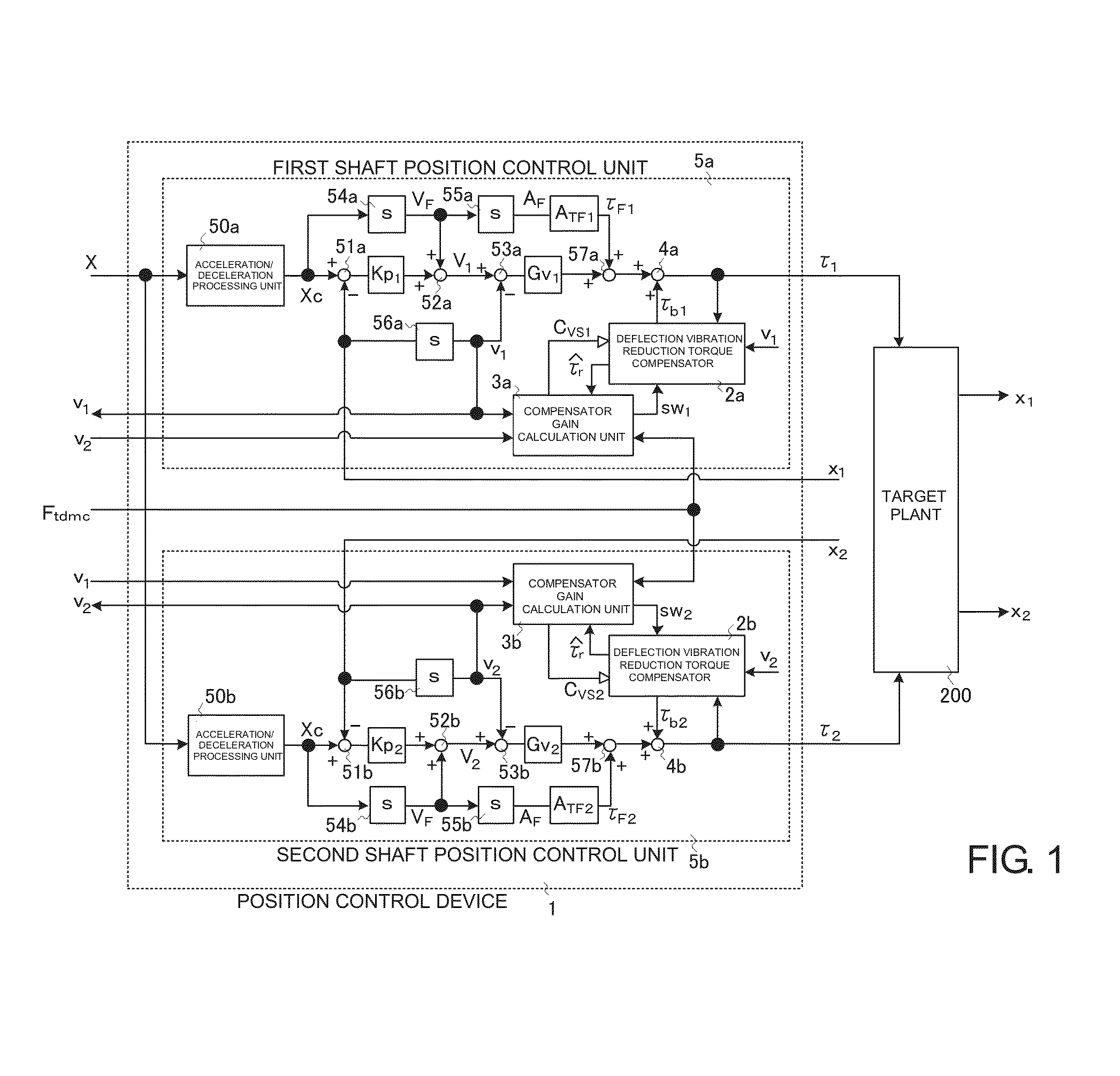
[0041]In the following, an embodiment of the present invention will be described referring to an example (hereinafter referred to as an embodiment). FIG. 1 is a block diagram showing one example of a position control device according to the present invention. In the following, only a difference from the above described conventional art will be described. This position control device is premised on a structure in which a first shaft position control unit and a second shaft position control unit are independently formed and the velocities of the respective shafts cannot be simultaneously detected on a real time basis.

[0042]Below, a first shaft position control unit 5a will be described. A second shaft position control unit 5b will not be described as the inside structure and structural elements thereof are the same as those of the first shaft position control unit 5a. Each of the shaft position control units 5a, 5b roughly includes a calculation unit for calculating a torque command v...


PUM


Abstract

A position control device for driving one control target, using two drive shafts, has position control units provided to the respective drive shafts. Each position control unit includes a calculation unit for calculating a torque command value before compensation, a deflection vibration reduction torque compensator for calculating a deflection torque estimate and calculating a deflection vibration reduction torque compensation amount, based on the deflection torque estimate and a deflection vibration reduction compensation gain, and a compensator gain calculation unit for outputting, upon receipt of a tandem control command, to the deflection vibration reduction torque compensator, a signal for outputting the deflection vibration reduction torque compensation amount and calculating the deflection vibration reduction compensation gain, and the each of the position control units outputs a value obtained by adding the deflection vibration reduction torque compensation amount to the torque command value before compensation as the torque command value.

Description

CROSS-REFERENCE TO RELATED APPLICATIONS[0001]The present invention claims priority under 35 U.S.C. §119 to Japanese Application No. 2015-056945, filed on Mar. 19, 2015, the entire content of which is incorporated herein by reference.BACKGROUND OF THE INVENTION[0002]1. Field of the Invention[0003]The present invention relates to a servo control device for controlling a shaft of an arm or the like of a machine tool or a robot, and in particular to tandem control for controlling one control target, using two motors.[0004]2. Description of the Related Art[0005]In a drive mechanism of a machine tool, a robot, or the like, when a control target, or a moving unit, is so large that a torque (a thrust force in the case of a linear motion type) of a single motor for driving a shaft of the moving unit is insufficient, tandem control may be executed by giving a command to two motors to drive a single control target, using two motors. In the tandem control state, respective motors (a rotation ty...

Claims


Application Information

Patent Timeline
Patent Type & Authority Applications(United States)
IPC IPC(8): G05B19/19H02P5/00
CPCG05B19/19G05B2219/42062H02P5/00H02P5/747G05B19/404G05B2219/41426G05B2219/49176
Inventor EGUCHI, SATOSHI
Owner OKUMA CORP
Why Eureka
Try Eureka