
Cable Management of Electric Powered Hydraulic Fracturing Pump Unit

Active Publication Date: 2016-09-22
US WELL SERVICS LLC
View PDF7 Cites 121 Cited by
  • Summary
  • Abstract
  • Description
  • Claims
  • Application Information

AI Technical Summary

Benefits of technology

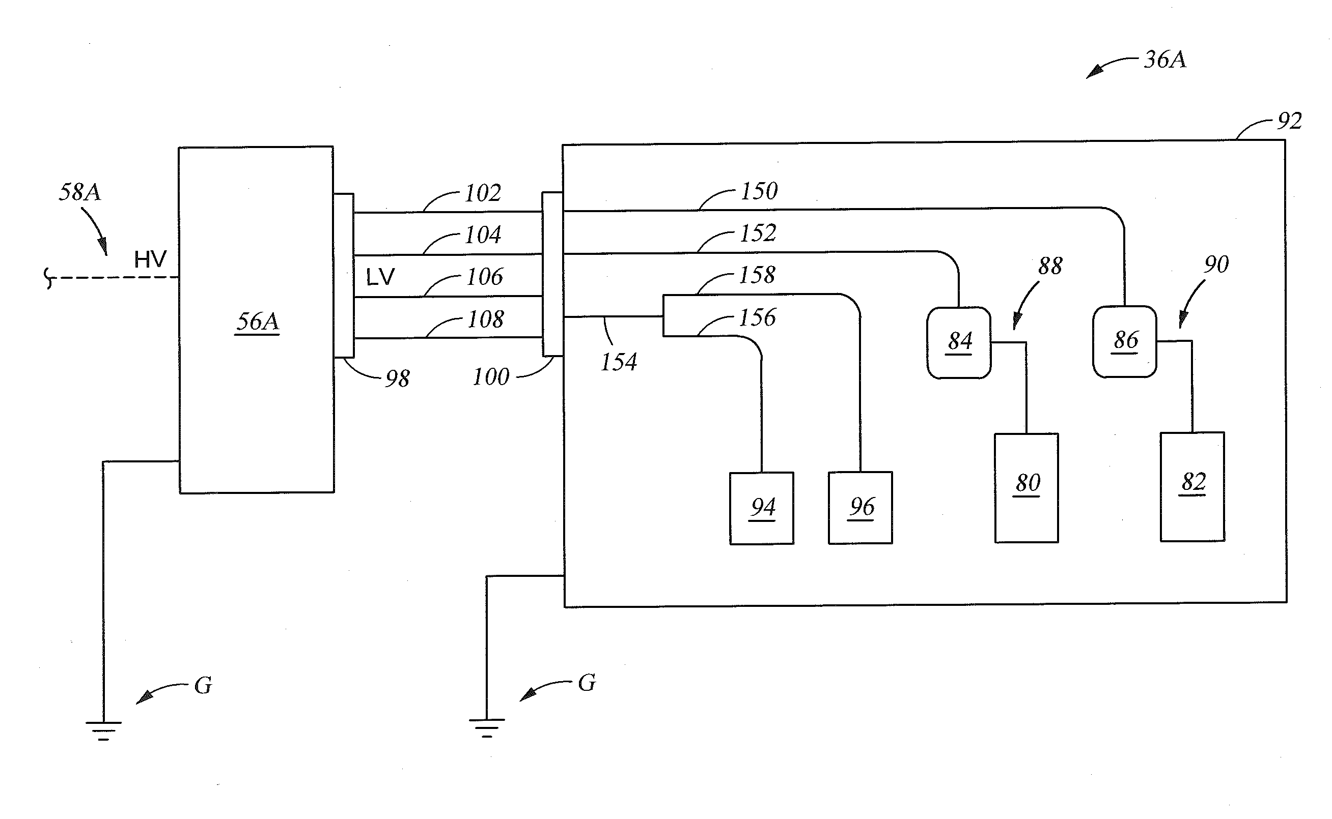
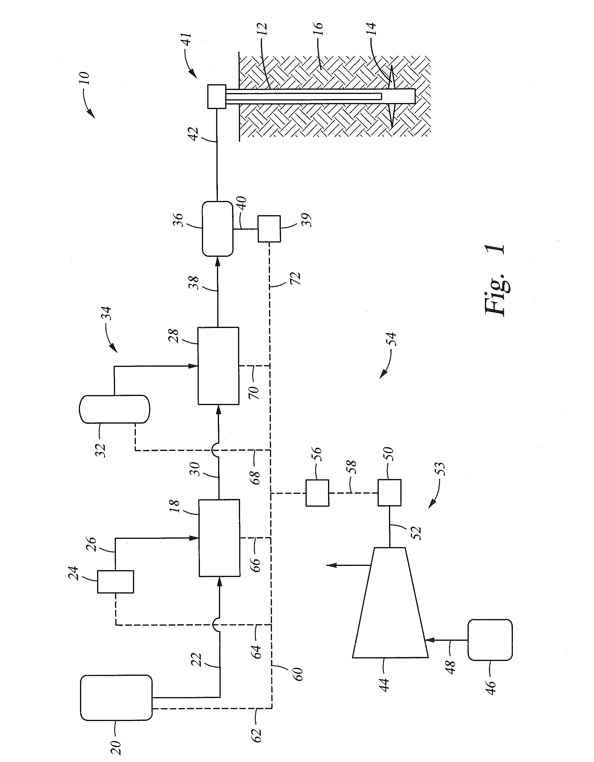
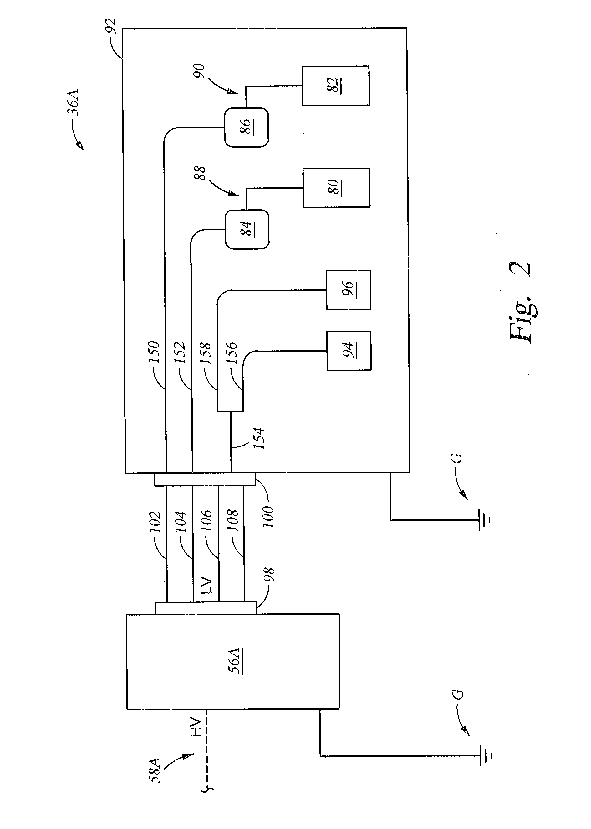
The patent is about a hydraulic fracturing system for fracturing underground formations. The system includes pumps, motors, a transformer, and electrical circuits. There are also cable assemblies and receptacles for transferring electricity between the transformer and motors. The system can have three phase electricity transferred between the transformer and motors in different cables. The receptacles can be strategically arranged so that cables with the same phase are adjacent one another. There is also a transformer ground receptacle and a pump ground receptacle for transferring grounding signals between the transformer and pumps. The system can also include a platform, enclosure, variable frequency drives, and a removable panel for easy access to the drives. The technical effects of the invention include improved efficiency, flexibility, and reliability of the hydraulic fracturing process.

Problems solved by technology

Electrical connection for this equipment is time consuming, and the current electrical distribution configurations require numerous cables that occupy valuable space.

Method used


Image

  • Cable Management of Electric Powered Hydraulic Fracturing Pump Unit
  • Cable Management of Electric Powered Hydraulic Fracturing Pump Unit
  • Cable Management of Electric Powered Hydraulic Fracturing Pump Unit

Examples


Embodiment Construction

[0020]The method and system of the present disclosure will now be described more fully hereinafter with reference to the accompanying drawings in which embodiments are shown. The method and system of the present disclosure may be in many different forms and should not be construed as limited to the illustrated embodiments set forth herein; rather, these embodiments are provided so that this disclosure will be thorough and complete, and will fully convey its scope to those skilled in the art. Like numbers refer to like elements throughout. In an embodiment, usage of the term “about” includes + / −5% of the cited magnitude. In an embodiment, usage of the term “substantially” includes + / −5% of the cited magnitude.

[0021]It is to be further understood that the scope of the present disclosure is not limited to the exact details of construction, operation, exact materials, or embodiments shown and described, as modifications and equivalents will be apparent to one skilled in the art. In the ...


PUM


Abstract

A hydraulic fracturing system includes a pump, an electrically powered motor for driving the pump, a trailer on which the pump and motor are mounted, and a transformer that steps down electricity for use by the motor. Electrical output from the transformer connects to a series of receptacles mounted onto a housing around the transformer. A similar set of receptacles is provided on the trailer and which are electrically connected to the motor. Power cables equipped with plugs on their opposing ends insert into the receptacles to close an electrical circuit between the transformer and pump.

Description

CROSS REFERENCE TO RELATED APPLICATIONS[0001]This application is a continuation of, and claims priority to and the benefit of, co-pending U.S. Provisional Application Ser. No. 62 / 156,303, filed May 3, 2015 and is a continuation-in-part of, and claims priority to and the benefit of co-pending U.S. patent application Ser. No. 13 / 679,689, filed Nov. 16, 2012, the full disclosures of which are hereby incorporated by reference herein for all purposes.BACKGROUND OF THE INVENTION[0002]1. Field of Invention[0003]The present disclosure relates to hydraulic fracturing of subterranean formations. In particular, the present disclosure relates to electrical components and connections connected to an electric hydraulic fracturing pump to minimize space and time requirements for rig up and rig down.[0004]2. Description of Prior Art[0005]Hydraulic fracturing is a technique used to stimulate production from some hydrocarbon producing wells. The technique usually involves injecting fluid into a wellb...

Claims


Application Information

Patent Timeline
IPC IPC(8): E21B43/26
CPCE21B43/26F04B23/04F04B47/06E21B43/2607
Inventor OEHRING, JARED
Owner US WELL SERVICS LLC
Learn More