
Applicator for superficial corneal medicaments

a corneal and application technology, applied in the field of applications of superficial corneal medicaments, can solve the problems of surface tension, irregular and variable results, easy to be disturbed, etc., and achieve the effect of setting up surface tension

Inactive Publication Date: 2016-09-22
1039578 B C LTD
View PDF4 Cites 6 Cited by
  • Summary
  • Abstract
  • Description
  • Claims
  • Application Information

AI Technical Summary

Benefits of technology

The present invention is about a fluid medicament applicator that includes a ring-shaped member with a tapered aperture. This ring member cradles a drop of fluid medicament until it is ready to be applied. The tapered aperture is designed to create surface tension on the fluid medicament, which causes the liquid to bulge outwardly beyond the ring member. This allows the liquid medicament to disperse over a surface area of a patient, disrupting cohesive forces in the liquid. The technical effect of this invention is to provide a more precise and controlled method of applying fluid medicament for medical purposes.

Problems solved by technology

From a physical perspective, the phenomenon of surface tension is due to unbalanced molecular cohesive forces in the liquid near its surface.
Nevertheless, because the cohesive forces are unbalanced, they can be easily disrupted.
The results, however, have been irregular and variable.
This is typically due to sponge contact with the eye, and other ancillary issues that include spillage, trauma to the exposed tissue, infections due to contact, and uneven or incomplete coverage of the surgical area.

Method used


Image

  • Applicator for superficial corneal medicaments
  • Applicator for superficial corneal medicaments
  • Applicator for superficial corneal medicaments

Examples


Embodiment Construction

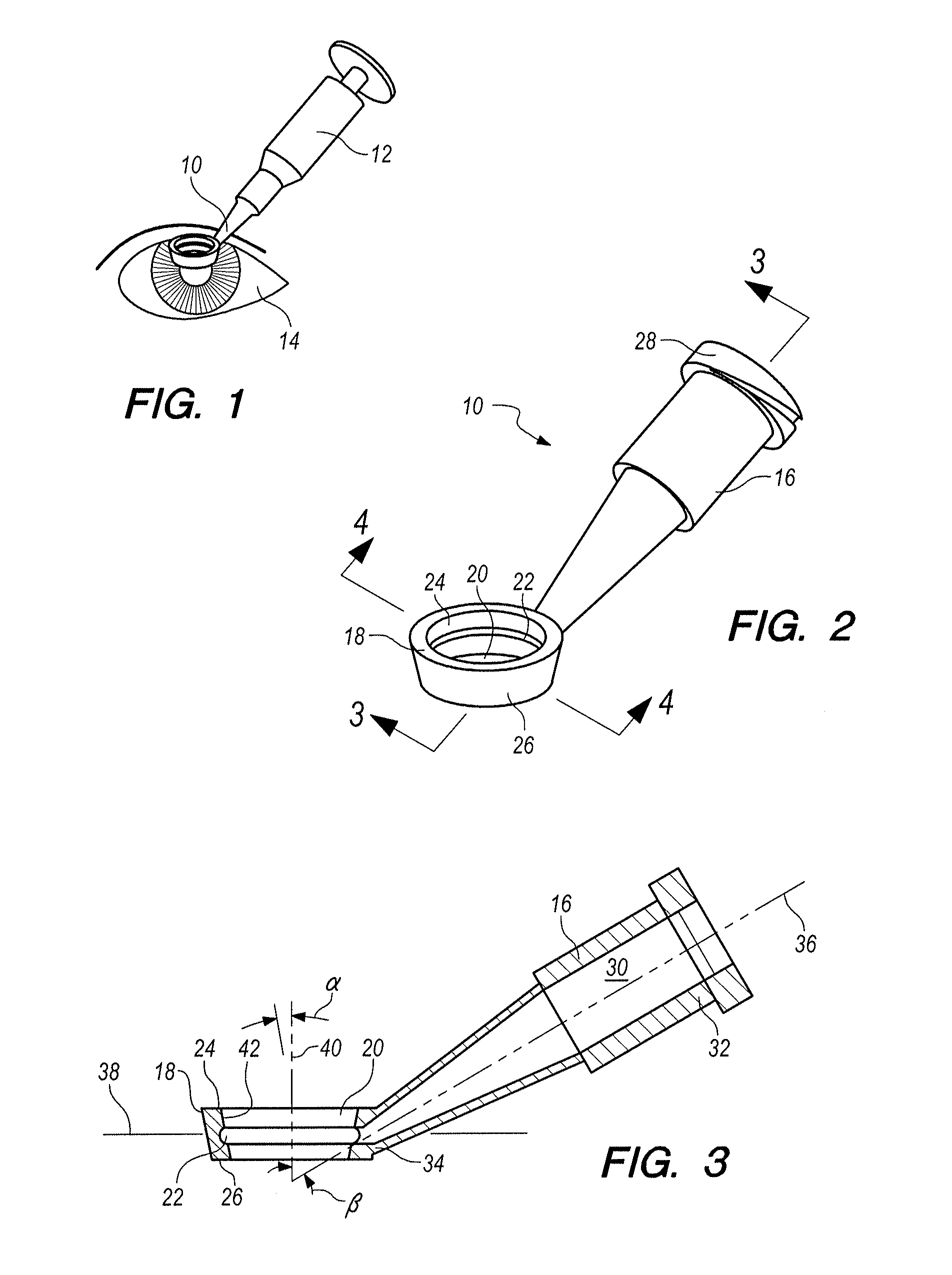
[0019]Referring initially to FIG. 1, a fluid medicament applicator in accordance with the present invention is designated 10 and shown in its intended operational environment. In particular, the applicator 10 is shown attached to a syringe 12 (source of the fluid medicament). Also, as shown, the applicator 10 is positioned to drop fluid medicament into the eye 14 of a patient.

[0020]In FIG. 2 it will be seen that the applicator 10 includes a hollow shaft 16 which is affixed to an annulus (ring member) 18. FIG. 2 also shows that the annulus 18 is formed with an aperture 20, and that a recess 22 is formed into the annulus 18 to surround the aperture 20 between an upper edge 24 of the annulus 18 and a lower edge 26 of the annulus 18. Further, a luer lock 28 is shown in FIG. 2 which is used for attaching the applicator 10 to the syringe 12.

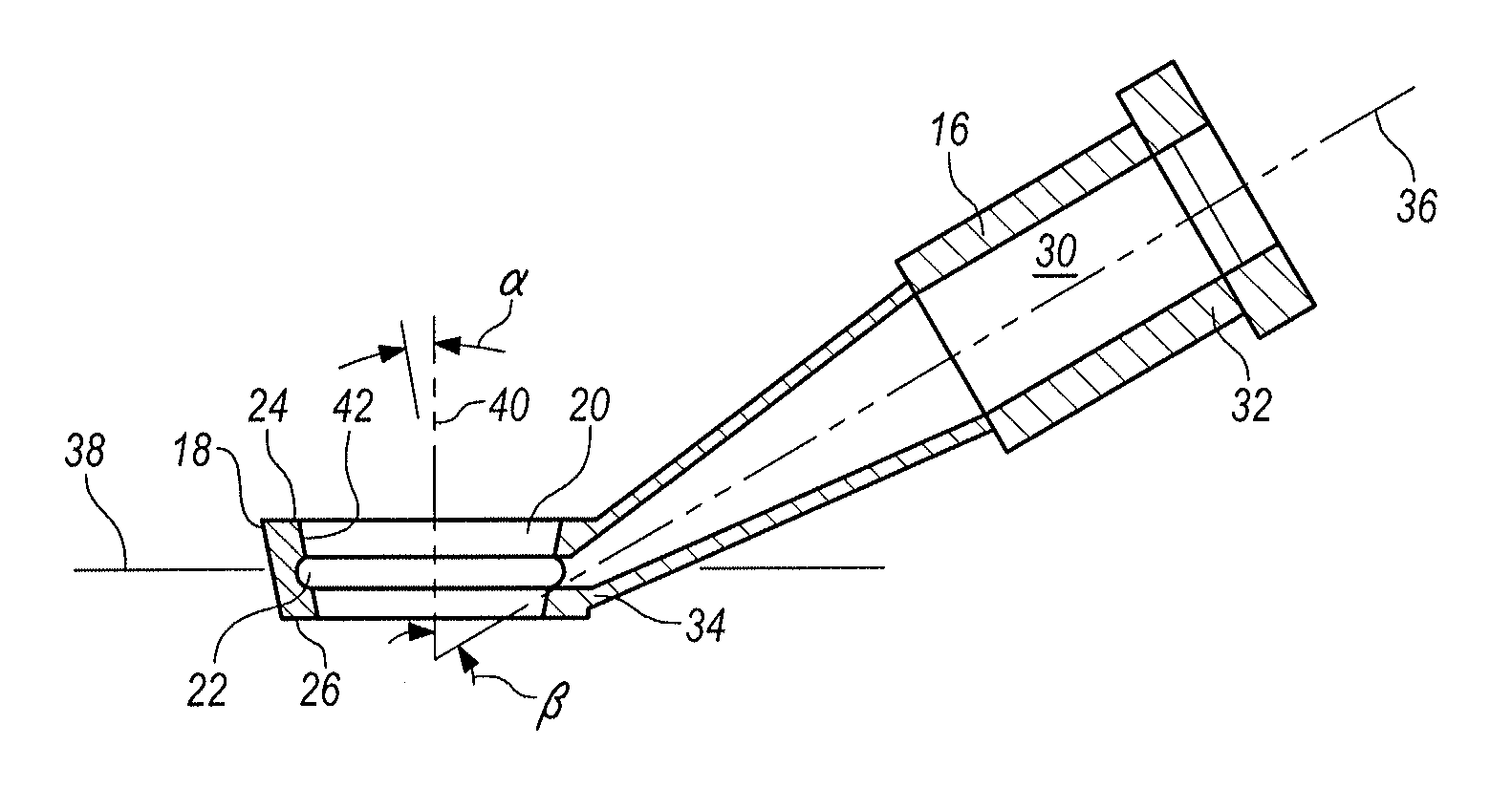
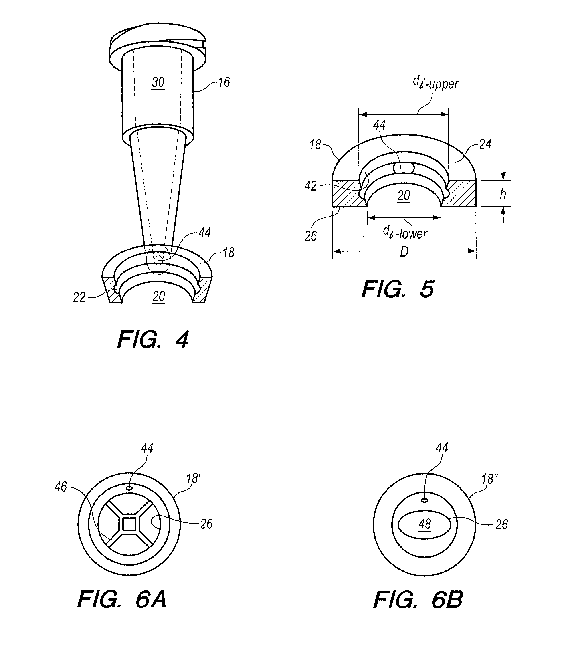
[0021]A more detailed presentation of a preferred configuration for the applicator 10 is shown in FIG. 3. There it will be seen that the shaft 16 is f...


PUM


Abstract

An applicator for applying fluid medicaments to a corneal surface of a patient, after surgery, includes a circular, ring-shaped member. The ring member creates an aperture which extends between parallel planes, with a wall surrounding the aperture as well as upper and lower openings into the aperture. The wall around the aperture is tapered, and there is a hole that extends through the wall. A hollow shaft is connected in fluid communication with the hole in the wall through which a fluid can be injected into the aperture. A bubble of the fluid can then be cradled in the aperture by the wall, and held therein by surface tension across the lower opening of the aperture. An application of the fluid bubble onto the patient's eye requires only contact between the fluid bubble and the eye, with no need for contact between the applicator and the eye.

Description

FIELD OF THE INVENTION[0001]The present invention pertains generally to systems and methods for applying fluid (liquid) drops to an exposed surface of a human eye. In particular, the present invention pertains to applicators for depositing drops of a liquid medicament on the corneal surface of a patient following a surgical procedure. The present invention is particularly, but not exclusively, useful as a disposable, non-contact device that applies a liquid medicament uniformly over a corneal surface area having predetermined dimensions.BACKGROUND OF THE INVENTION[0002]It is well known that very small amounts of fluid, when unrestrained, will form into droplets. Rain drops are a familiar example of this development, as are drops from a leaky faucet. It is also well known that the creation of drops is the result of a physical phenomenon known as surface tension.[0003]By definition, surface tension is a property possessed by liquid surfaces whereby they appear to be covered by a thin ...

Claims


Application Information

Patent Timeline
Patent Type & Authority Applications(United States)
IPC IPC(8): A61F9/00
CPCA61F9/0026A61F9/0017A61F9/0008A61F9/008
Inventor LIN, DAVID TAT-CHILIN, STEPHANIE LEI-CHING
Owner 1039578 B C LTD
Learn More