Temporary, modular, hip joint with neck-length modification mechanism

Inactive Publication Date: 2016-09-15
BURNIKEL BRIAN G +1
View PDF5 Cites 14 Cited by
  • Summary
  • Abstract
  • Description
  • Claims
  • Application Information

AI Technical Summary

Benefits of technology

The patent describes a temporary, adjustable, modular hip joint prosthesis. It comprises a neck element with a mechanism that allows the neck length to be changed after the stem has been implanted. The adjustment base and the slide unit can be rotated to change the length of the neck and increase pressure on the cup. The length change is indicated by reference points on the adjustment base and adjacent edge of the side walls of the slide unit. The invention provides a flexible solution for adjusting the length of the hip joint prosthesis after implantation.

Problems solved by technology

Contact of the surface of the prosthetic ball with the surface of the cup presents several continuing challenges: the need for some type or form of lubrication to ensure smooth contact between the surfaces and some means to distribute the hip load on the surface of the hip ball uniformly to the surface of the cup, rather than having undesirable pressure points from the position of the ball in the cup during actual use.

Method used


Image

  • Temporary, modular, hip joint with neck-length modification mechanism
  • Temporary, modular, hip joint with neck-length modification mechanism
  • Temporary, modular, hip joint with neck-length modification mechanism

Examples


example i

Neck Length Modification Mechanism

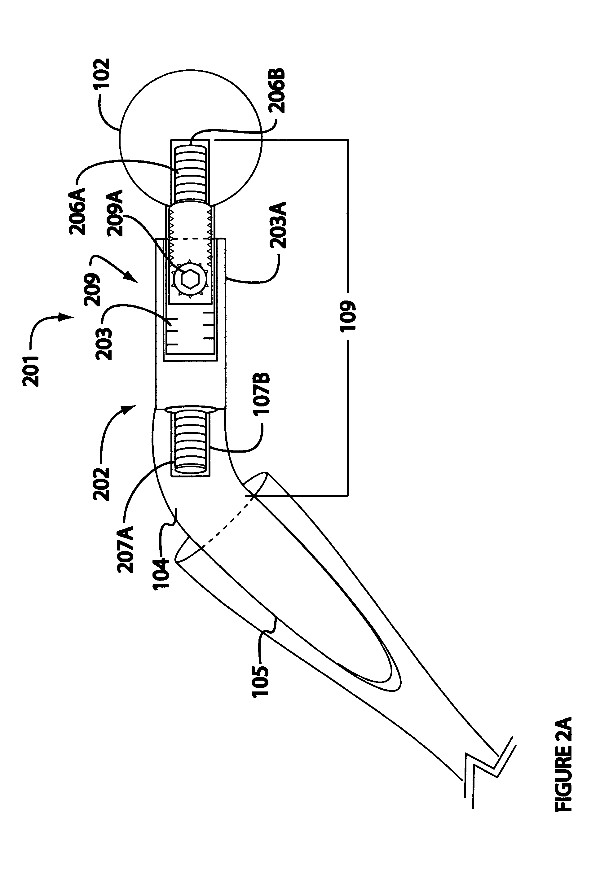
[0042]As illustrated in FIGS. 2A and 2B, the neck length modification mechanism 201 comprises a fixed or static component, the adjustment base 202, and a longitudinally moveable component, the slide travel component 203A. The adjustment base 202 further comprises the slide unit chamber, or run 203B. The slide unit chamber 203B comprises a back wall 210A, a first and a second side wall 210D and 210E, respectively, a floor 210B and an open top 210C.

[0043]In addition the adjustment base comprises the adjustment base stud 207A. The adjustment base stud 207A is adapted to engage the second receptacle 107B thereby securely connecting the adjustment base to the body, and consequently to the stem.

[0044]The slide travel component 203A comprises a box-like structure, the travel gear box 211. The travel gear box 211 is described and limited by a back wall 212A, a front wall 212B, a first side wall 212C and a second side wall 212D, and an open bottom 212E. The ...

example ii

Alternative Neck Length Modification Mechanism

[0061]FIG. 3 provides a schematic, side view of the neck length modification mechanism 301 of second example. The purpose of the alternative mechanism in Example II is effectively the same as that for the in Example I: to provide the surgeon with a temporary hip prosthetic device the length of the neck of which can be modified without removal of the entire prosthesis so that the optimum neck length may be more accurately and more rapidly determined during the course of the implant procedure. Although the both functional and structural similarities exist between the mechanism of Example I and of Example II, the two mechanisms differ to a degree such that, except for the ball 102. Parts and functions in this example are assigned new names and index numbers.

[0062]The second neck length modifying mechanism 301 comprises three main elements: a rotatable, adjustable base 302, a pressure disk 303, and the male, threaded drive axle 308. Note, th...


PUM


Abstract

A temporary neck for a hip joint prosthesis comprising a mechanism that will allow the length of the temporary neck to be varied while in place, during implant surgery and after the stem and base of a permanent prosthesis have been positioned. In one best mode the variation in length is driven by rotating a pinion gear that engages a rack gear connected to the interior of the side walls of a moveable unit, and the ball is connected by a stud to the front wall of the moveable unit; thus the ball moves the same distance as the moveable unit, and that distance is a direct function of gear tooth spacing and number of rotations of the gear. In an alternative mechanism, a threaded drive axle (worm gear) moves in response rotation an adjustment base (wheel gear) in which the base comprises a drive disk with a female, threaded bore. The axle is secured to the pressure disk at one end and free at the other. The position of the drive disk (hence bore) is static; thus as the drive disk rotates and the threads are engaged, the pressure disk moves and the ball moves with it. Both devices include visual references to determine precisely the distance that has been traveled (generally in mm).

Description

PRIORITY[0001]This Application claims priority of U.S. Provisional Application No. 61 / 967,315 filed Mar. 17, 2014 and which Provisional Application is hereby incorporated in its entirety.FIELD OF THE INVENTION[0002]The claimed invention is generally related to orthopaedic surgery. More specifically, it is related to fitting prosthetic hip joints, and more specifically it is a modification of the neck segment of a temporary, prosthetic hip joint and related method to determine the optimum length of the neck of the permanent joint by use of a temporary prosthesis with an extendable / retractable neck determine the optimum length of the neck of the permanent prosthesis.INTRODUCTION[0003]Growth of Medical Speciality and Commercial Growth[0004]The current, basic hip joint prosthesis traces to the work of Sir John Charnley, British orthopaedic surgeon working at Wrightington Hospital. By the 1970's, Charnley's design effectively replaced all of the prosthetic designs in use; earlier designs...

Claims


Application Information

Patent Timeline
IPC IPC(8): A61F2/46F16H19/04A61F2/36
CPCA61F2/4657A61F2/3609A61F2/4684F16H19/04A61F2310/00023A61F2002/4658A61F2220/0025A61F2310/00017A61F2002/3645A61F2002/30507A61F2002/30523A61F2002/3055A61F2002/30593
Inventor BURNIKEL, BRIAN G.BURNIKEL, ALEXANDER J.
Owner BURNIKEL BRIAN G
Why Eureka
Try Eureka