Intermittent UWB receiver

Active Publication Date: 2016-09-08
COMMISSARIAT A LENERGIE ATOMIQUE ET AUX ENERGIES ALTERNATIVES
View PDF12 Cites 3 Cited by
  • Summary
  • Abstract
  • Description
  • Claims
  • Application Information

AI Technical Summary

Benefits of technology

The present invention is a UWB impulse signal receiver that uses a rake processor and a detection module to estimate received symbols. The synchronization preamble is followed by a payload containing a group of symbols. The receiver comprises an RF stage with a baseband processing stage which includes a rake processor and detection module. The control module is adapted to control the positions of the acquisition windows in order to scan the reception interval during the synchronization phase. The processing is preferably an integration of the baseband signal during the acquisition window. The RF stage comprises a low noise amplifier and first and second quadrature mixing stages, and can optionally also include second and fourth analog / digital converters. The receiver can power off the RF stage outside the acquisition windows. The invention also includes an improvement method to optimize the acquisition window positioning for the payload reception phase. The technical effects of the invention include improved synchronization and detection of UWB signals.

Problems solved by technology

The lack of internationally harmonized regulations on the one hand and the multiplication of the UWB standards for different types of application, on the other hand, lead to the prevision of receivers able to operate in several frequency bands.
On the other hand, in a non-coherent receiver, there is no available a priori knowledge of the impulse response of the channel or, at the very least, of the total impulse response insofar as the phase of this response can be unknown.
However, the drawback of the intermittent IR-UWB receiver such as described in the above-mentioned paper is that it must operate continuously during the synchronization phase.
Thus, throughout the duration of this phase, the RF stage of the IR-UWB receiver must be powered and consequently consumes energy.

Method used


Image

  • Intermittent UWB receiver
  • Intermittent UWB receiver
  • Intermittent UWB receiver

Examples


Embodiment Construction

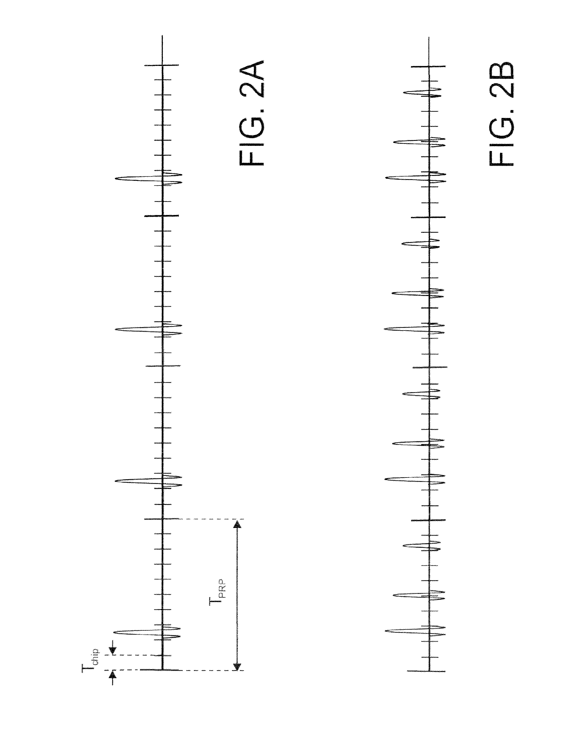
[0047]A receiver intended to receive a UWB impulse signal (IR-UWB receiver), such as the one described in the introductory part will again be considered thereafter. The UWB impulse signal is divided into transmission intervals, each transmission interval being itself divided into chips. A symbol (typically a binary symbol) is transmitted over a transmission interval by means of a sequence of unit impulses (which can be reduced to a single impulse) distributed on the different chips of the interval. The symbol modulates said sequence using a PPM and / or PAM (or even QAM) modulation.

[0048]FIG. 5 represents the architecture of an intermittent IR-UWB receiver according to an embodiment of the invention.

[0049]The receiver 500 comprises an RF stage 501, and a baseband processing stage 502.

[0050]The RF stage 501 comprises a low noise amplifier 510, one or more demodulation stages, to bring the received signal into baseband. For example, the RF stage can comprise a demodulation stage at an i...


PUM


Abstract

A UWB impulse receiver including an RF stage followed by a baseband processing stage. The baseband processing stage includes a Rake filter including a plurality of time fingers, each finger including an integrator of the baseband signal during an acquisition window, a control module, and a detection module estimating the received symbols from the integration results. During a synchronization phase, the control module drives respective positions of the acquisition windows associated with the different fingers, to scan at a reception interval, the RF stage only operating, in a course of the synchronization phase, during the plurality of acquisition windows.

Description

TECHNICAL FIELD[0001]The present invention relates to the field of UWB (Ultra Wide Band) receivers and more particularly the duty cycled UWB impulse receivers.STATE OF PRIOR ART[0002]The ultra wide band (UWB) telecommunication systems, whether of the impulse (IR-UWB) type or not must transmit in certain well-defined specific frequency bands, depending on regional regulations, and having a frequency spectrum of a minimum width (500 MHz in the United States).[0003]The lack of internationally harmonized regulations on the one hand and the multiplication of the UWB standards for different types of application, on the other hand, lead to the prevision of receivers able to operate in several frequency bands.[0004]FIG. 1 shows by way of example the frequency plan used in the IEEE 802.15.4a and IEEE 802.15.16 standards, in the 2-6 GHz band. It is reminded that the IEEE 802.15.4a and IEEE 802.15.16 standards both use a UWB impulse transmission, the IEEE 802.15.4a standard being relative to t...

Claims


Application Information

Patent Timeline
IPC IPC(8): H04B1/7183H04B1/7075H04B1/7115
CPCH04B1/7183H04B1/7115H04B1/70758H04B2201/70707H04B2201/7073H04B2201/7163H04B2201/70979H04B1/7163
Inventor HAMEAU, FREDERICMASSON, GILLESOUVRY, LAURENT
Owner COMMISSARIAT A LENERGIE ATOMIQUE ET AUX ENERGIES ALTERNATIVES
Why Eureka
Try Eureka