
Well fracturing systems with electrical motors and methods of use

a technology of electrical motors and well fracturing, which is applied in the direction of fluid removal, earthwork drilling and mining, borehole/well accessories, etc., can solve the problems of relative inefficiency of internal combustion engines, high operating costs, and use of diesel engines, and achieve the effect of limiting the scope of attached claims

Active Publication Date: 2016-09-08
STEWART & STEVENSON
View PDF6 Cites 198 Cited by
  • Summary
  • Abstract
  • Description
  • Claims
  • Application Information

AI Technical Summary

Benefits of technology

The patent describes a system for stimulating oil or gas production from a wellbore using an electrically powered fracturing system. The system includes a hydraulic fracturing pump unit, an electrically powered hydraulic blender unit, a hydration unit, and a system control unit. The control unit separately controls each of the units, allowing for individual control of parameters such as pump speed, motor speed, and fluid flow rate. The system also includes a data channel for communication between the hydraulic fracturing unit and the electrical fracturing blender, allowing for real-time monitoring and control of the fracturing process. The technical effects of the patent include improved efficiency and control over the fracturing process, reduced emissions, and improved safety.

Problems solved by technology

Using diesel engines, however, has serious disadvantages, including the relative inefficiency of the internal combustion engine and the fact that its operation is costly.
In addition, off-road diesel engines of the types used for hydraulic fracturing are noisy while pumping, limiting the areas in which they may be used.
Also, diesel engines have many moving parts and require continuous monitoring, maintenance, and diagnostics.
Ancillary subsystems are typically driven hydraulically in traditional diesel-driven systems, which also contribute to other operational problems.
DC motor commutators and brushes may wear rapidly under this condition.
Despite the potential advantages associated with electrical motors of both types, and the continuing need for improvement, the use and control of hydraulic fracturing operations using electrical motors has not been successfully implemented in practice.

Method used


Image

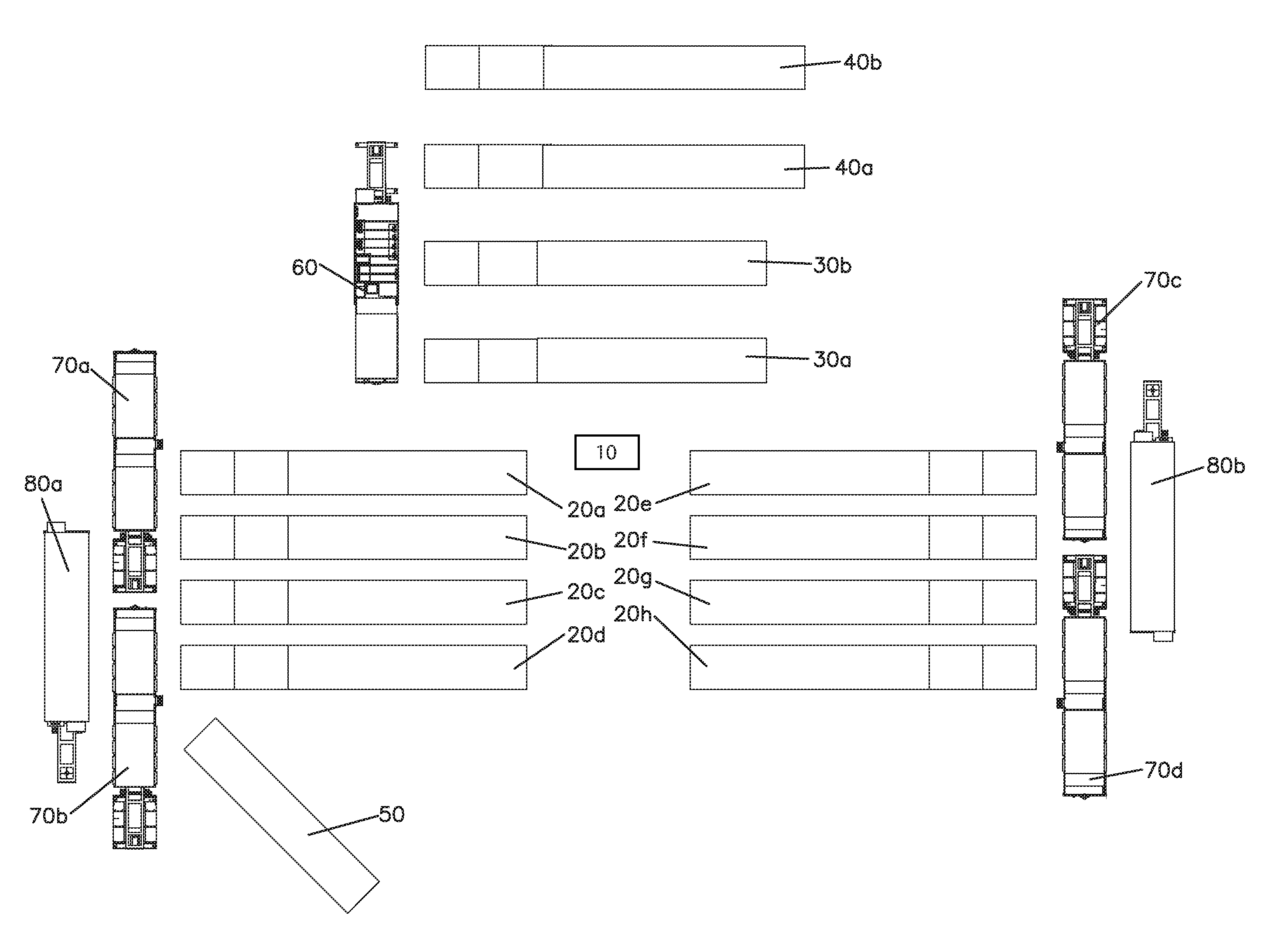
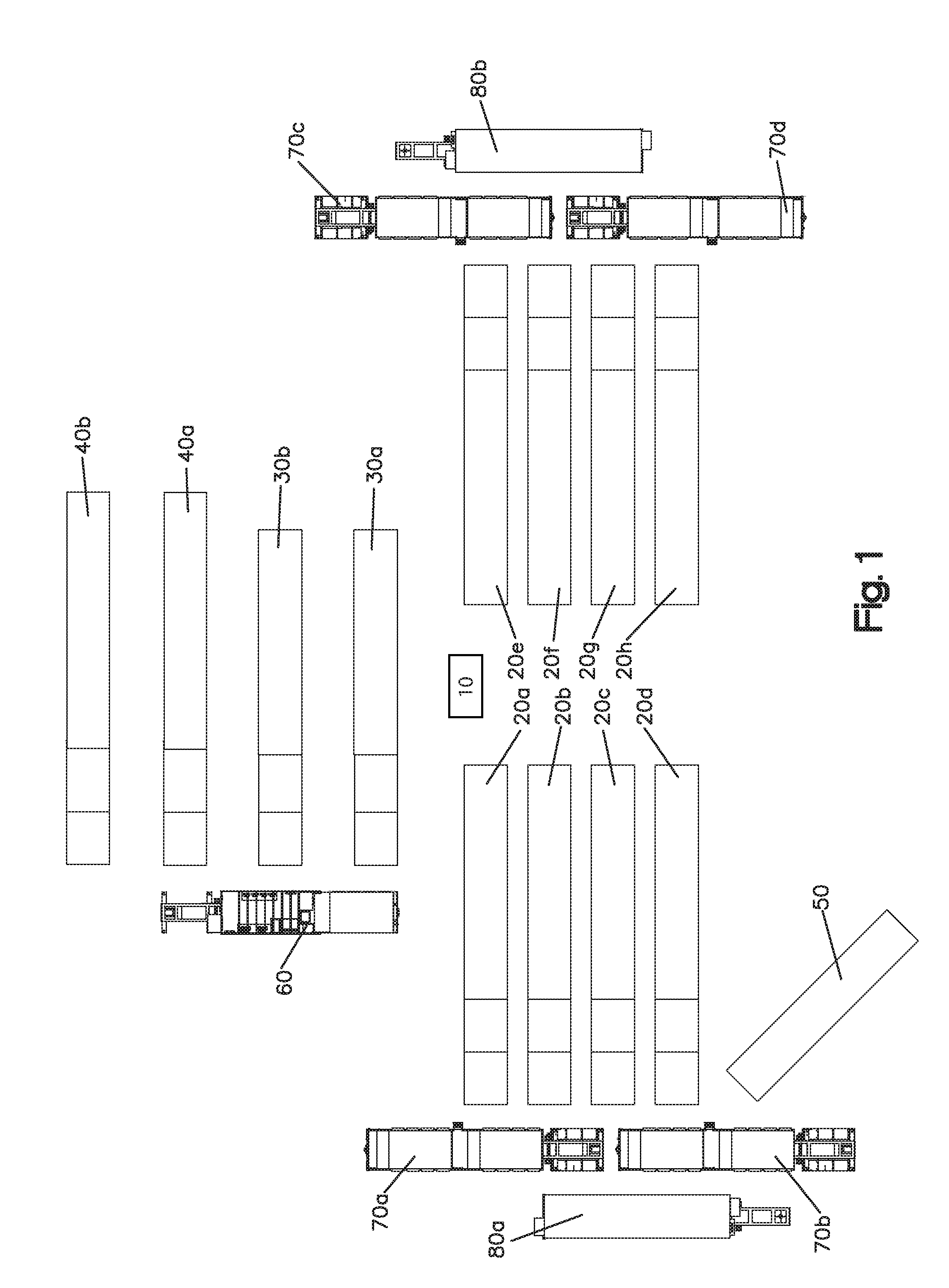
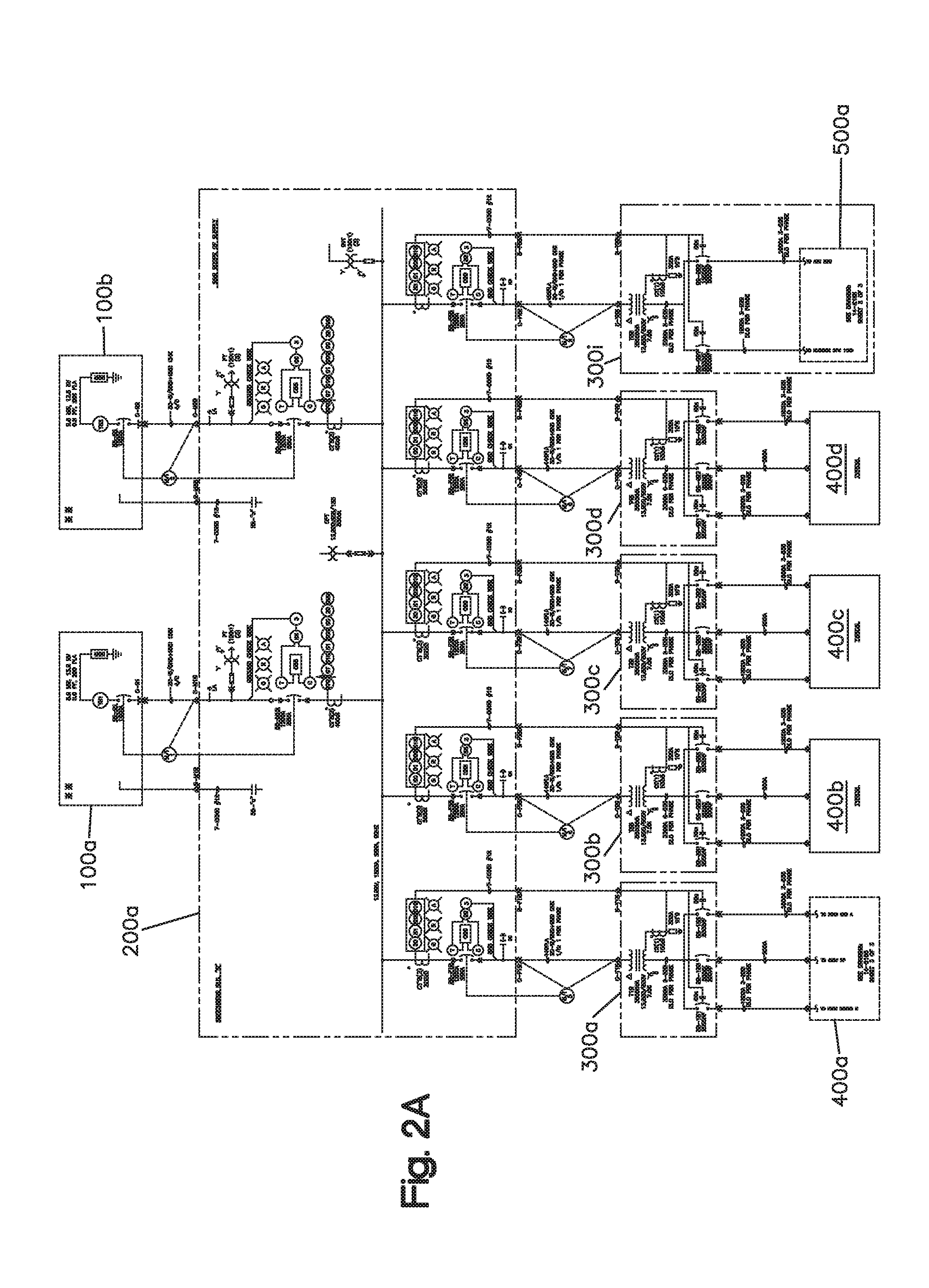
  • Well fracturing systems with electrical motors and methods of use
  • Well fracturing systems with electrical motors and methods of use
  • Well fracturing systems with electrical motors and methods of use

Examples


Embodiment Construction

[0036]The following detailed description is provided to assist the reader in gaining a comprehensive understanding of the methods, apparatuses, and / or systems described herein. Various changes, modifications, and substantial equivalents of the systems, apparatuses and / or methods described herein will be apparent to those of ordinary skill in the art. In certain cases, descriptions of well-known functions and constructions have been omitted for increased clarity and conciseness.

[0037]The control of AC motors provides several advantages over traditional diesel-driven, including variable gear ratio powertrains based on the more precise, continuous speed control. During operation, the described methods and systems enable the AC motors to be controlled with specific speed settings based on a specific speed input and can be incremented or decremented in single RPM (revolutions per minute) intervals without interruption.

[0038]This following description also relates to a method to control a...


PUM


Abstract

A system for stimulating oil or gas production from a wellbore includes a hydraulic fracturing pump unit having one or more hydraulic fracturing pumps driven by one or more electrical fracturing motors, a variable frequency drive (VFD) controlling the electrical fracturing motors, a fracturing pump blower unit driven by a blower motor, and a fracturing pump lubrication unit having a lubrication pump driven by a lubrication motor and a cooling fan driven by a cooling motor. The system may further include a blender unit and a hydration unit. A system control unit may control the operational parameters of the system.

Description

CROSS-REFERENCE TO RELATED APPLICATIONS[0001]This application claims the benefit of U.S. Provisional Application No. 62 / 128,291, filed on Mar. 4, 2015, which is incorporated herein by reference in its entirety for all purposes.BACKGROUND[0002]1. Field[0003]The following description relates to remotely monitoring and controlling electrical motors in oil and gas well stimulation hydraulic fracturing applications. For example, an apparatus and method allows an operator to remotely monitor and control, through wired connections and / or wirelessly, one or more alternating current motors in oil and gas well stimulation hydraulic fracturing applications.[0004]2. Description of Related Art[0005]Hydraulic fracturing is the process of injecting treatment fluids at high pressures into existing oil or gas wells in order to stimulate oil or gas production. The process involves the high-pressure injection of “fracking fluid” (primarily water, containing sand or other proppants suspended with the a...

Claims


Application Information

Patent Timeline
IPC IPC(8): E21B44/00E21B43/26
CPCE21B43/26E21B44/00E21B21/062E21B43/2607
Inventor PAYNE, MARKLIN, HAOMINROBERTSON, TOM
Owner STEWART & STEVENSON
Learn More