
Dual mode cooling pump with over-running clutch

a dual-mode cooling pump and clutch technology, which is applied in the direction of mechanical actuated clutches, machines/engines, liquid fuel engines, etc., can solve the problems of accessory products subject to the same limitations of size, number of components and cost, and the size, cost and cost limitations of accessory products, so as to increase the effectiveness of the engine cooling system, increase fuel mileage, and reduce cost

Inactive Publication Date: 2016-09-01
BORGWARNER INC
View PDF6 Cites 6 Cited by
  • Summary
  • Abstract
  • Description
  • Claims
  • Application Information

AI Technical Summary

Benefits of technology

The present invention is an improvement over existing coolant pumps and provides a better engine cooling system, helps save fuel, is cheaper, reduces harmful emissions, and can be placed in more places in the engine compartment.

Problems solved by technology

These accessory products are also being supplied today and are subject to the same limitations as to size, number of components and cost.
These accessory products are subject to similar limitations of size, components and cost.

Method used


Image

  • Dual mode cooling pump with over-running clutch
  • Dual mode cooling pump with over-running clutch
  • Dual mode cooling pump with over-running clutch

Examples


Embodiment Construction

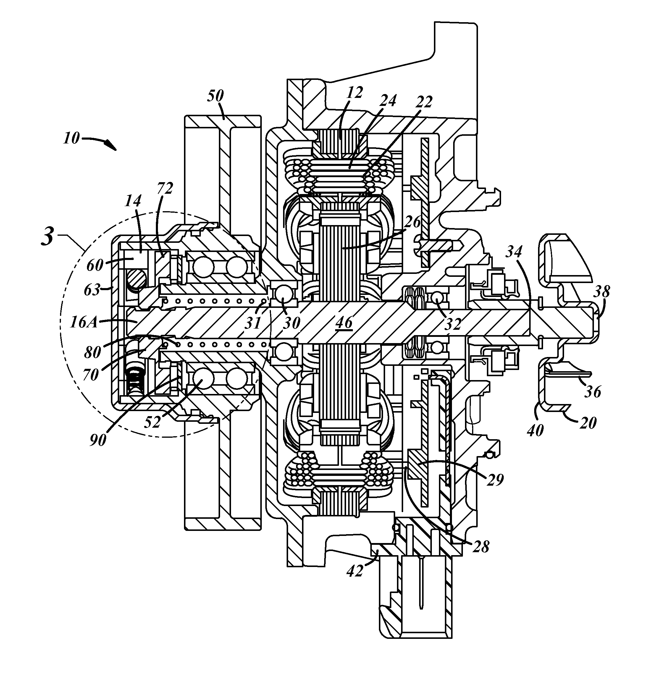
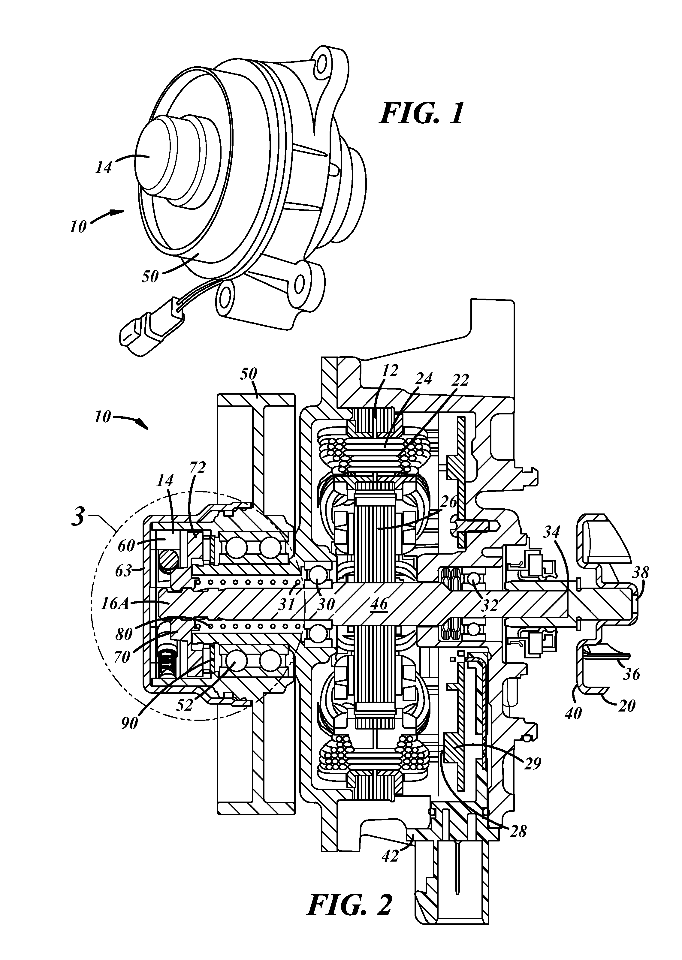
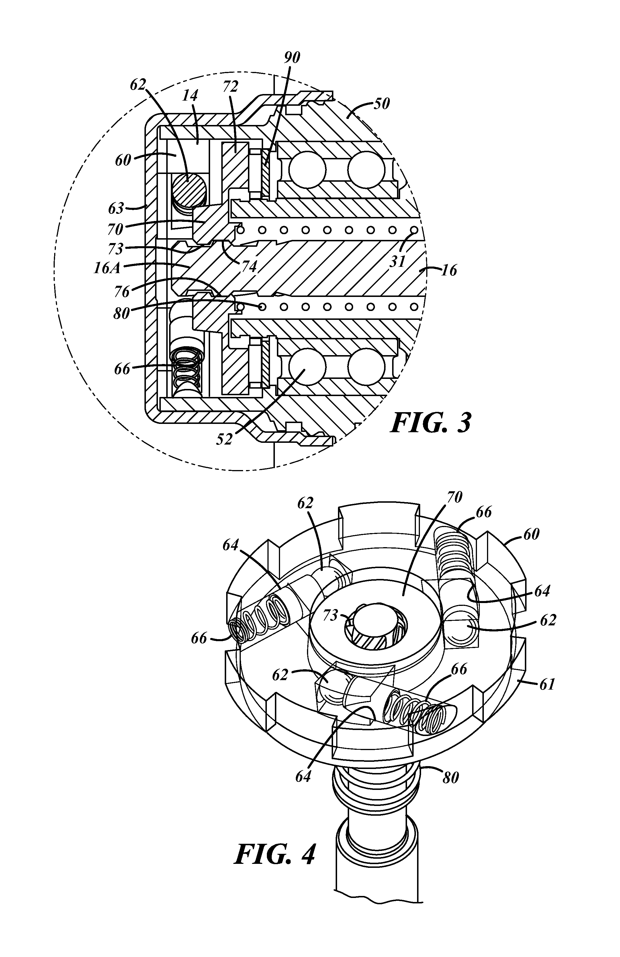
[0018]As shown in FIGS. 1-3, a preferred dual mode embodiment of the invention 10 includes an electric mechanism motor 12, an overrunning clutch mechanism 14, a central shaft member 16 and an impeller member 20. The dual mode coolant pump including an electric motor and overrunning clutch and has two separate modes of operation, namely electrical and mechanical.

[0019]The electric motor mechanism 12 includes an electric motor 22, which preferably is a brushless DC motor. The mechanism 12 includes a stator 24, a rotor 26, and is actuated electronically through wire lead 28 and electronic circuit board 29. The rotor 26 is directly connected to the shaft member 16 and, when energized, rotates the shaft member and impeller 20 at a desired speed. The rotational speed is determined by an electric control unit (ECU) of the engine or vehicle which receives inputs from a variety of sensors. (Representative ECU 25 and sensors 27 are depicted in FIG. 8.) The sensors read numerous operating cond...


PUM


Abstract

System for circulating the flow of coolant in a vehicle engine cooling system. A dual mode mechanism has an electric motor and an overrunning clutch mechanism which selectively rotate an impeller at a desired speed to circulate the coolant. The impeller is rotated by the electric motor, but can also be selectively rotated by the overrunning clutch mechanism. An electronic control can be utilized to selectively control the electric motor and overrunning clutch, together with control logic.

Description

TECHNICAL FIELD[0001]The present invention is related to systems for controlling the flow of coolant in a vehicle, particularly utilizing a coolant pump which has both electrical and mechanical modes of operation.BACKGROUND OF THE INVENTION[0002]The great majority of vehicles today utilize engines run on an organic fuel, such as gasoline. Due to the heat developed by the engines during use, various cooling systems have been developed for maintaining the temperature of the engine within acceptable limits. These cooling systems typically circulate a coolant fluid through the engine, radiator and other components in order to extract heat from the engine.[0003]The need today for vehicles to meet higher gas mileage standards and also meet stricter standards on toxic emissions has resulted in the development of various assemblies, components and engine systems which have attempted to meet these standards. At the same time, as vehicles get smaller to reduce weight and the number of compone...

Claims


Application Information

Patent Timeline
Patent Type & Authority Applications(United States)
IPC IPC(8): F01P5/12F04D29/22F04D29/041F16D41/00F04D29/42F04D29/52F04D25/06F01P3/20F04D29/18F04D29/043
CPCF01P5/12F04D29/181F04D29/22F04D29/041F16D41/00F04D29/426F04D29/528F04D25/068F01P3/20F04D29/043F01P7/164F01P2005/125F16D41/088F16D48/02F16D2023/123F04D13/022F04D13/06F04D15/0066F04D13/021
Inventor VANZUILEN, DAVID M.
Owner BORGWARNER INC
Learn More