
Apparatus for transferring specimens of biological material between laboratory automation systems placed at different heights

a technology for biological material and automation systems, applied in the direction of conveyor parts, transportation and packaging, control devices of conveyors, etc., can solve the problems of insufficient single laboratory room, inconvenient solution, and the apparatus in question cannot operate in alternating manner, etc., to achieve the effect of speeding up

Active Publication Date: 2016-09-01
INPECO
View PDF0 Cites 5 Cited by
  • Summary
  • Abstract
  • Description
  • Claims
  • Application Information

AI Technical Summary

Benefits of technology

The invention provides an apparatus that can move conveying devices containing specimens in both directions at once, making the process faster and more efficient compared to existing solutions. This means that specimens can be exchanged between different automation systems more quickly.

Problems solved by technology

Automation systems for the movement of test tubes in an analysis laboratory have increasingly large dimensions, and now a single laboratory room is often not sufficient to contain the entire system and all analysis modules interfacing therewith.
This solution is not very practical, first because it may keep the operator in charge constantly engaged, who could instead carry out other tasks in the laboratory, and it would also be preferable to ensure a supply of specimens to the system where they should be transferred, which occurs immediately when there is a need, regardless of the more or less regular movements, from one room to the other, of the operator as the test tube carrier.
However, in the known solutions, the apparatus in question can only operate in an alternating manner, as an elevator at certain times and as a descender at others, as there is only one path available for both the ascent and the descent of conveying devices.

Method used


Image

  • Apparatus for transferring specimens of biological material between laboratory automation systems placed at different heights
  • Apparatus for transferring specimens of biological material between laboratory automation systems placed at different heights
  • Apparatus for transferring specimens of biological material between laboratory automation systems placed at different heights

Examples


Embodiment Construction

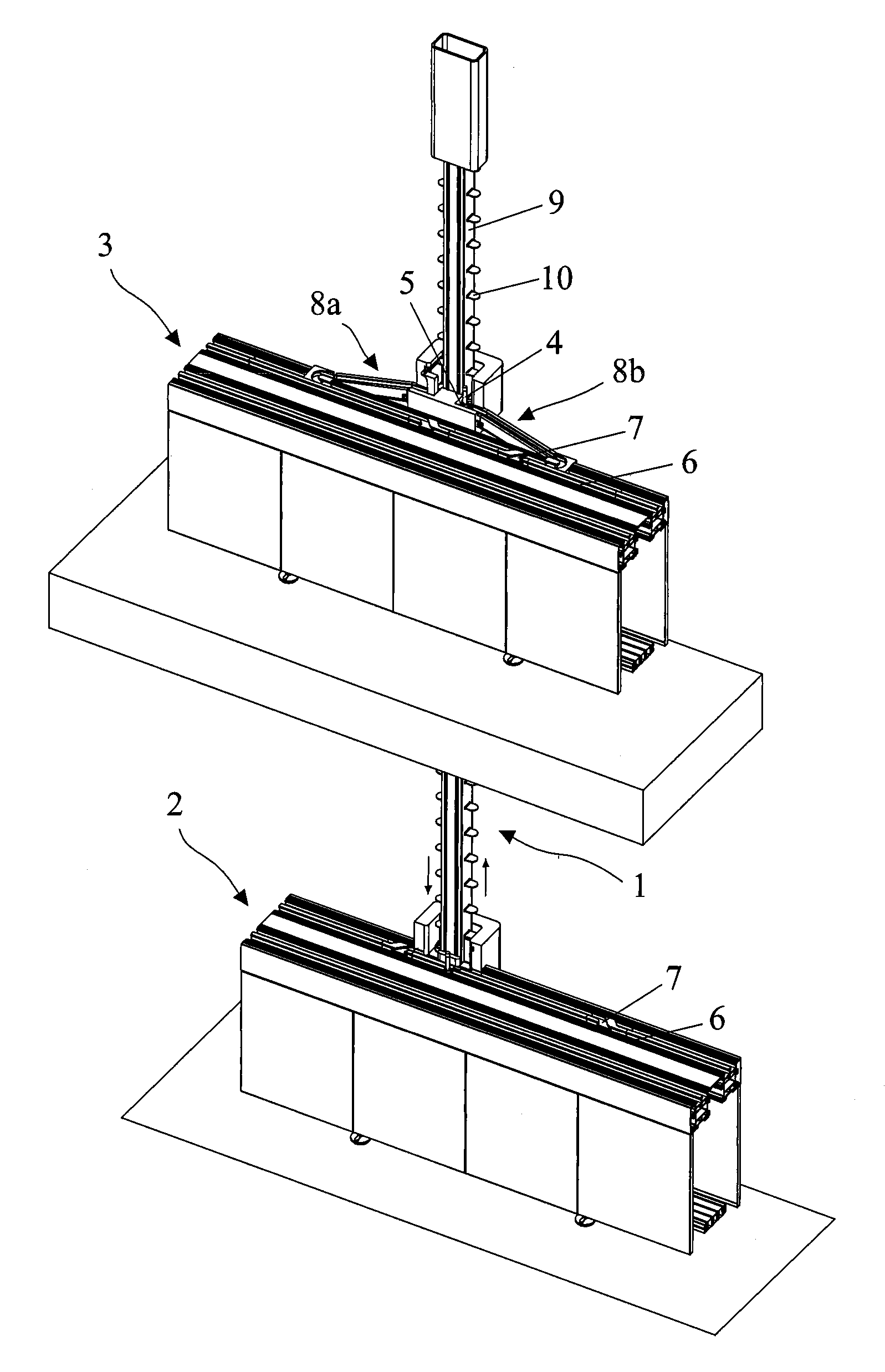
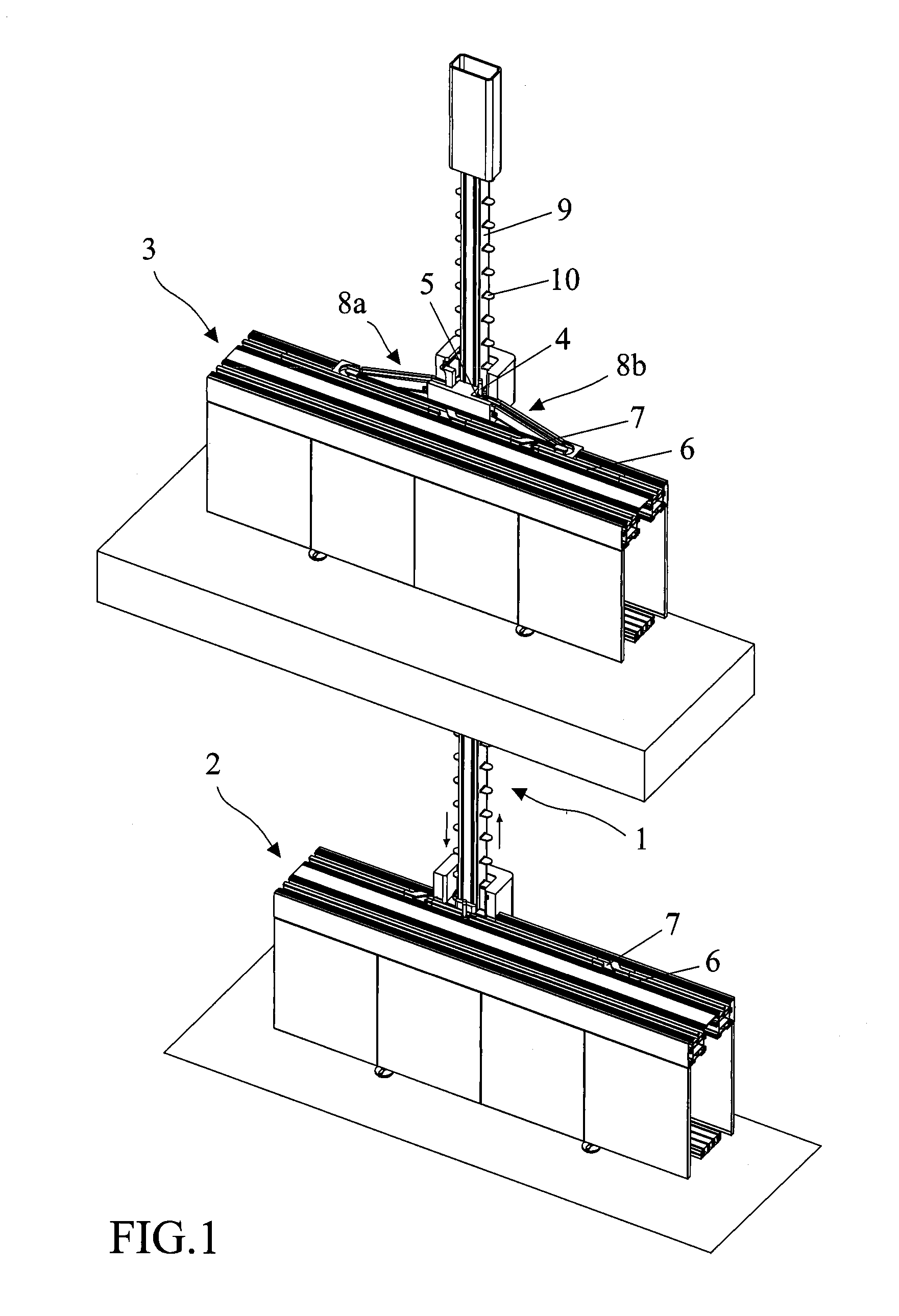
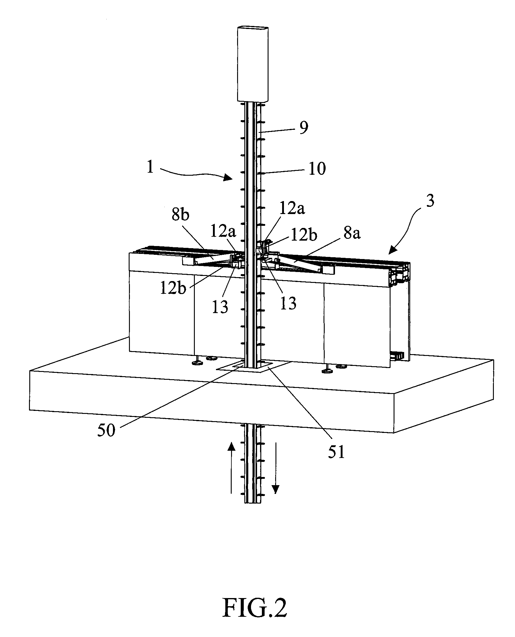
[0020]An apparatus 1 connects together two different automation systems 2, 3, for example placed in two separate rooms (located one above the other) of an analysis laboratory (FIG. 1). Apparatus 1 extends through both rooms, through a suitable cavity 50 made in the ceiling of the room on the lower floor, and is used to transfer specimens of biological material, contained in test tubes 4, between systems 2 and 3 in both directions. Cavity 50 may be protected by a layer 51 of insulating and fire-retardant material, such as rock wool (FIG. 2).

[0021]Each test tube 4 is in turn contained in conveying devices 5 for a single test tube 4, and may indifferently be capped or uncapped. According to the specific needs of the analysis modules connected to systems 2 and 3, the possibility to also transfer empty conveying devices 5 along apparatus 1 may also be included.

[0022]Each conveying device 5 is adapted to keep the respective test tube 4 in a vertical position, as shown for example in FIG. ...


PUM


Abstract

There is described an apparatus for the transfer of conveying devices of containers of biological products between laboratory automation systems placed at different heights. Said apparatus comprises a motor-driven belt arranged transversely with respect to said automation systems. Shelves are fixed to said motor-driven belt for accommodating said conveying devices during said transfer. Said conveying devices are loaded / unloaded on / from said shelves of said apparatus by the action of pushers. Said belt allows, by means of its rotation, a simultaneous bidirectional transfer, both in ascent and descent, of conveying devices from one automation system to the other.

Description

[0001]The present invention relates to an apparatus for the transfer of specimens of biological material between laboratory automation systems placed at different heights.BACKGROUND OF THE INVENTION[0002]Automation systems for the movement of test tubes in an analysis laboratory have increasingly large dimensions, and now a single laboratory room is often not sufficient to contain the entire system and all analysis modules interfacing therewith.[0003]In most laboratories, multiple automation systems are therefore arranged, separate from one another, in different rooms possibly even located on different floors of the laboratory itself. Each system may be interfaced, according to the space available, with a certain amount of assay modules, also different from one another from system to system.[0004]However, it is frequent the case in which a same specimen is to be taken over and analyzed, in a sequence, by modules that interface with separate automation systems located in different ro...

Claims


Application Information

Patent Timeline
IPC IPC(8): B65G47/57B65G43/08
CPCB65G47/57B65G2201/0261B65G43/08B65G17/123G01N2035/0406G01N2035/0465G01N2035/0467G01N2035/0484
Inventor PEDRAZZINI, GIANANDREA
Owner INPECO
Learn More