
Liquid crystal display panel with switchable viewing angle and driving method thereof

a technology rotating viewing angle, which is applied in the field of liquid crystal display panel with rotating viewing angle and driving method thereof, can solve the problems of inconvenient operation, increase manufacturing cost, thickness, energy consumption of liquid crystal display panel, etc., and achieve the effect of convenient operation and simple structur

Active Publication Date: 2016-08-25
SHENZHEN CHINA STAR OPTOELECTRONICS TECH CO LTD
View PDF2 Cites 12 Cited by
  • Summary
  • Abstract
  • Description
  • Claims
  • Application Information

AI Technical Summary

Benefits of technology

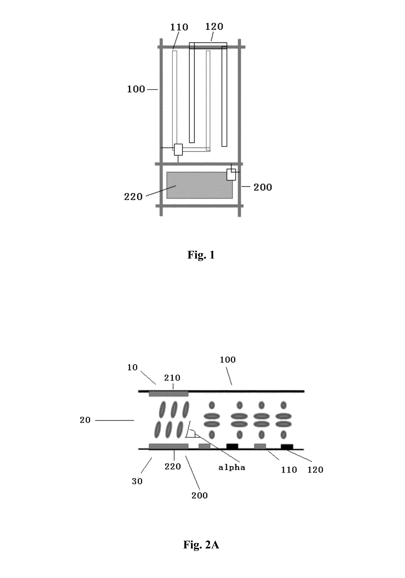
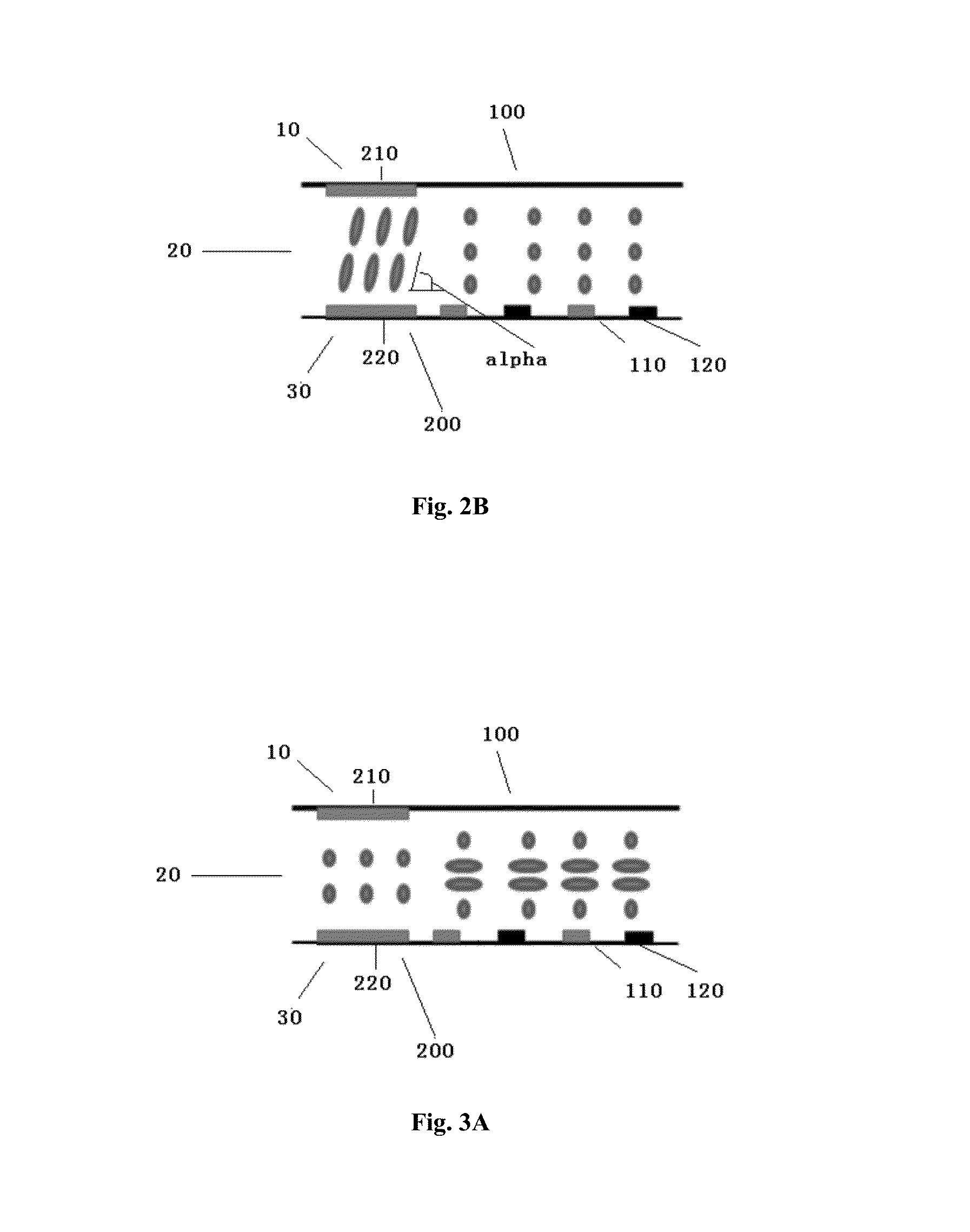
The present disclosure provides a liquid crystal display panel with a switchable viewing angle that has a simpler structure and is more convenient to operate. The panel comprises an upper substrate, a lower substrate, and a liquid crystal layer provided between them. The panel has a main pixel region and a sub-pixel region. When no bias voltage is applied to the upper substrate electrodes in the sub-pixel region, liquid crystal molecules corresponding to the sub-pixel region do not deflect, resulting in large viewing angle light leakage. When a bias voltage is applied, the liquid crystal molecules corresponding to the sub-pixel region deflect to a flat state, resulting in wide viewing angle display. The driving method involves applying no bias voltage in the narrow viewing angle display mode and applying a bias voltage in the wide viewing angle display mode. Compared with conventional solutions, the present invention has reduced manufacturing costs and energy consumption.

Problems solved by technology

Such a procedure is inconvenient to operate.
This system will undoubtedly increase manufacturing costs, thickness, and energy consumption of the liquid crystal display panel.
This double-layer liquid crystal display panel will also increase manufacturing costs, thickness, and energy consumption of the liquid crystal display panel.
Obviously, none of the above liquid crystal display panels can satisfy the requirements of a portable electronic apparatus for size or energy consumption.

Method used


Image

  • Liquid crystal display panel with switchable viewing angle and driving method thereof
  • Liquid crystal display panel with switchable viewing angle and driving method thereof
  • Liquid crystal display panel with switchable viewing angle and driving method thereof

Examples


Embodiment Construction

[0031]The present disclosure is based on hybrid light distribution technology. In order to explain the purposes, technical solutions, and advantages of the present disclosure more explicitly, the present disclosure will be further described in detail with reference to the accompany drawings.

[0032]The present disclosure will be explained in detail with reference to FIGS. 1-3 in the following.

[0033]FIG. 1 is a partial top view of a display area of a liquid crystal display panel according to a first embodiment of the present disclosure. As is in the prior art, the panel comprises an upper substrate 10 and a lower substrate 30 parallel with each other, and a liquid crystal layer 20, preferably negative liquid crystal material, provided between the upper substrate 10 and the lower substrate 30.

[0034]In the present embodiment, the upper substrate 10 can comprise an upper substrate glass layer, an upper substrate quarter-wave plate, an upper substrate half-wave plate, and an upper substrat...


PUM

PropertyMeasurementUnit
Electrical conductoraaaaaaaaaa
Electric potential / voltageaaaaaaaaaa

Abstract

Disclosed is a liquid crystal display panel with a switchable viewing angle and a driving method thereof. A pixel unit located in a display area of the liquid crystal display panel comprises: a main pixel region, which is horizontally aligned, wherein pixel electrodes and common electrodes are alternately arranged on the lower substrate and spaced from one another; and a sub-pixel region, which is perpendicularly aligned, wherein upper substrate electrodes and corresponding pixel electrodes are arranged below the upper substrate and on the lower substrate, respectively. When no bias voltage is applied to the upper substrate electrodes in the sub-pixel region, liquid crystal molecules corresponding to the sub-pixel region do not deflect, such that large viewing angle light leakage occurs in the sub-pixel region, thereby achieving narrow viewing angle display. When a bias voltage is applied to the upper substrate electrodes in the sub-pixel region, the liquid crystal molecules corresponding to the sub-pixel region deflect to a flat state, such that large viewing angle light leakage ceases in the sub-pixel region, thereby achieving wide viewing angle display.

Description

[0001]The present application claims benefit of Chinese patent application CN 201410856071.1, entitled “Liquid crystal display panel with switchable viewing angle and driving method thereof” and filed on Dec. 31, 2014, the entirety of which is incorporated herein by reference.FIELD OF THE INVENTION[0002]The present disclosure relates to a technology of liquid crystal displays, and in particular, to a liquid crystal display panel with a switchable viewing angle and a driving method thereof.BACKGROUND OF THE INVENTION[0003]A viewing angle range (viewing angle for short) is an important performance index of a liquid crystal display panel. It is necessary for a liquid crystal display panel to vary a polarization state of light transmitted therethrough via adjusting orientation of liquid crystal molecules, so as to achieve a display function. Due to influences of optical anisotropy of liquid crystal molecules, a liquid crystal display device has a smaller viewing angle than a cathode-ray...

Claims


Application Information

Patent Timeline
IPC IPC(8): G02F1/1343G02F1/1337G02F1/133
CPCG02F1/133711G02F2001/134372G02F1/133G02F1/1343G02F1/139G02F1/133753G02F2001/134345G02F2001/133757G02F1/13439G02F1/134363G02F1/13306G02F1/134309G02F1/134372G02F1/134381G02F1/1323G02F2413/04G02F2413/06G02F1/133638G02F1/133757G02F1/134345
Inventor TANG, YUEJUN
Owner SHENZHEN CHINA STAR OPTOELECTRONICS TECH CO LTD
Learn More