
Touch panel and touch display device comprising the same

a technology of touch display device and touch electrode, which is applied in the field of touch panel, can solve the problems of reducing poor linearity and precision of touch electrodes in the periphery of the touch panel, and consequently increasing the cost of a single piece of glass. , to achieve the effect of improving the cutting ratio of panel glass and improving the touch precision

Inactive Publication Date: 2016-08-11
INNOLUX CORP
View PDF7 Cites 15 Cited by
  • Summary
  • Abstract
  • Description
  • Claims
  • Application Information

AI Technical Summary

Benefits of technology

The present invention provides a touch panel with improved touch precision and increased panel glass cutting ratio. This is achieved through the placement of touch electrodes in different sizes on the substrate, where the area of touch electrodes on the peripheral touch area is smaller than that of the touch electrodes on the central touch area. Additionally, the touch electrodes closest to the intersecting portion of the two edges have the smallest area. The design also includes border electrodes on the border area with a smaller area than the touch electrodes on the central touch area and the same area as the touch electrodes on the peripheral touch area. Various driving methods, such as different pulse widths and gains, can further improve touch precision. The present invention also provides a touch display device with the touch panel.

Problems solved by technology

Accordingly, the touch electrodes in the periphery of the touch panel often encounter problems of poor linearity and precision.
However, the widening will result in the reduction of the cutting ratio of panel glass and the cost for a single piece of glass will increase consequently.

Method used


Image

  • Touch panel and touch display device comprising the same
  • Touch panel and touch display device comprising the same
  • Touch panel and touch display device comprising the same

Examples


embodiment 1

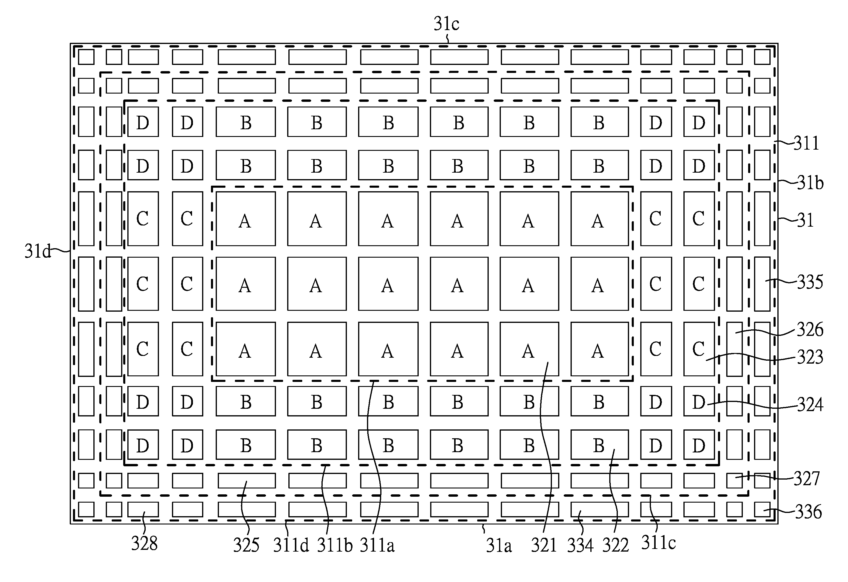
[0034]FIG. 3 is a top view of a touch panel of Embodiment 1 of the present invention. A touch panel of the present embodiment includes a substrate 31 having a surface 311 and a first edge 31a and a second edge 31b in which the first edge 31a is adjacent to the second edge 31b. A central touch area 311a and a first peripheral touch area 311b surrounding the central touch area 311a and outside the central touch area 311a are disposed on the surface 311 of the substrate 31. A plurality of first touch electrodes 321 are disposed on the substrate 31 and on the central touch area 311a. A plurality of second touch electrodes 322 are disposed on the substrate 31 and arranged on the first peripheral touch area 311b between the central touch area 311a and the first edge 31a. A plurality of third touch electrodes 323 are disposed on the substrate 31 and arranged on the first peripheral touch area 311b between the central touch area 311a and the second edge 31b. A plurality of fourth touch elec...

embodiment 2

[0060]As shown in FIG. 8, the structure and the driving mode of the touch panel in the present embodiment is similar to that of Embodiment 1. However, the touch panel of the present embodiment further includes a second peripheral touch area 311c surrounding the first peripheral touch area 311b and disposed outside the first peripheral touch area 311b. The second peripheral touch area 311c can be between the first peripheral touch area 311b and the border area 311d. Accordingly, the touch panel of the present embodiment further includes: a plurality of fifth touch electrodes 325 disposed on the second peripheral touch area 311c between the first peripheral touch area 311b and the first edge 31a; a plurality of sixth touch electrodes 326 disposed on the second peripheral touch area 311c between the first peripheral touch area 311b and the second edge 31b; and at least one seventh touch electrode 327 disposed on the second peripheral touch area 311c closest to an intersecting portion o...

embodiment 3

[0067]As shown in FIG. 9, the present embodiment provides a touch display device including a display panel 92 and a touch panel 91 disposed on the display panel 92. The touch panel 91 may be one of the touch panels described above in the aforesaid embodiments. The display panel 92 may be a conventional display panel, such as a liquid crystal display panel or an organic light-emitting diode display panel.

[0068]The touch panel and the display panel made in the aforesaid embodiments of the present invention may be applied to any conventional electronic devices requiring touch control function, especially to touch display devices, such as display devices, mobile phones, notebooks, video cameras, cameras, music players, portable navigation devices, televisions, and so forth.


PUM


Abstract

A touch panel including a substrate having a first edge and a second edge adjacent to the first edge, wherein a central touch area and a first peripheral touch area are disposed on the substrate; a plurality of first touch electrodes disposed on the central touch area; a plurality of second and third touch electrodes disposed on the first peripheral touch area; and a fourth touch electrode disposed on the first peripheral touch area closest to an intersecting portion of the first edge and the second edge, wherein an area of at least one first touch electrode is greater than that of at least one second touch electrode and that of at least one third touch electrode, and an area of at least one second touch electrode and that of at least one third touch electrode are both greater than that of the fourth touch electrode.

Description

CROSS REFERENCE TO RELATED APPLICATION[0001]This application claims the benefits of the Chinese Patent Application Serial Number 201510061892.0, filed on Feb. 6, 2015, the subject matter of which is incorporated herein by reference.BACKGROUND OF THE INVENTION[0002]1. Field of the Invention[0003]The present invention relates to a touch panel and particularly to a touch panel in which the linearity and touch precision of the periphery of the touch panel may be improved and the cutting ratio of panel glass may be increased to reduce the production cost of the panel.[0004]2. Description of Related Art[0005]In recent years, with the trend to the development of user-friendly and simplified operation technology, display devices with touch panels have been widely used in daily life. Since users can input signals by touching the touch panels with fingers or other articles, the users' dependence on other input devices, such as keyboards, mice, remote controllers, and the like, may be diminish...

Claims


Application Information

Patent Timeline
Patent Type & Authority Applications(United States)
IPC IPC(8): G06F3/041
CPCG06F3/0412G06F3/0416G06F3/04164G06F3/04166G06F3/0443G06F3/0448
Inventor WENG, TSAN-PO
Owner INNOLUX CORP
Learn More