
Method and device for checking the integrity of load bearing members of an elevator system

Active Publication Date: 2016-08-11
KONE CORP
View PDF13 Cites 14 Cited by
  • Summary
  • Abstract
  • Description
  • Claims
  • Application Information

AI Technical Summary

Benefits of technology

The patent describes a method for detecting damage to a load-bearing member using a pulse injection technique. The method is not affected by factors like winding and load distribution, reducing the risk of false alarms and making it more reliable. A cross-check is performed when a possible damage condition is detected by comparing data from different tensile elements. The elapsed time between the injection of the pulse and the detection of the damage is measured accurately, allowing for the location of the damage to be determined. The method also has a blind region that can be eliminated with the use of bridged embodiments. The source pulse has a small duration to avoid overlapping with the feedback pulse and a low amplitude to avoid the need for insulation.

Problems solved by technology

In some embodiments (e.g. grounded tensile elements), it is expected that undamaged and uniform tensile elements provide no feedback, and hence a feedback pulse may reveal a damage, for example a non-uniformity of the internal structure which generates a reflection of the source pulse.
Hence, when the feedback of a tensile element deviates from the feedback of another element, it is likely that at least one of the two tensile elements is damaged.

Method used


Image

  • Method and device for checking the integrity of load bearing members of an elevator system
  • Method and device for checking the integrity of load bearing members of an elevator system

Examples


Embodiment Construction

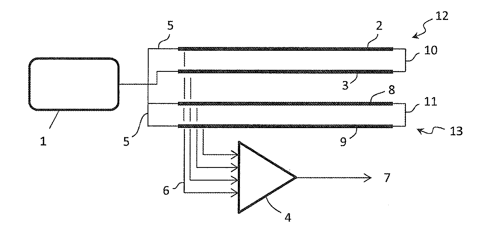
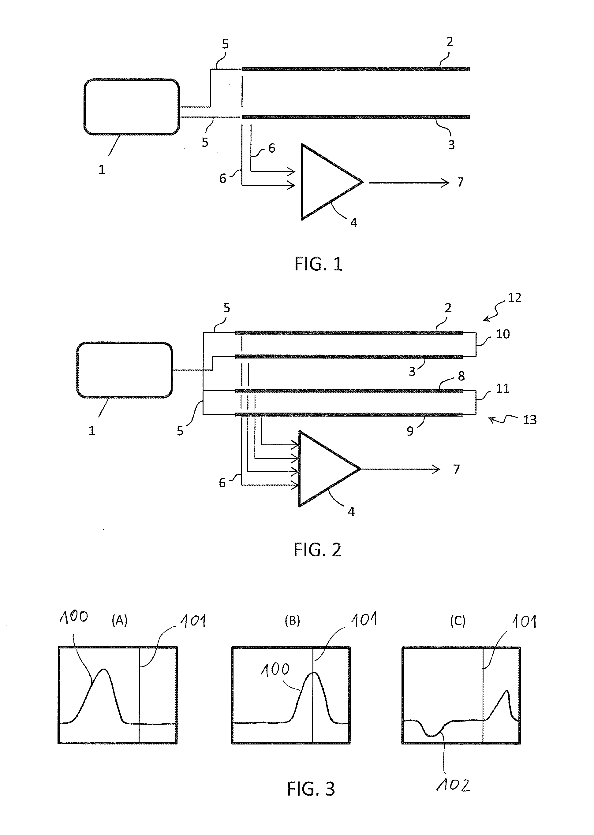
[0047]Referring to FIG. 1, the block 1 denotes a pulse generation unit, which may include one or more pulse generators, connected to tensile elements of a load-bearing member of an elevator. Said tensile elements are for example steel cords 2, 3. A comparator 4 is also electrically connected to said steel cords 2, 3.

[0048]The unit 1 can launch a pulse through the steel cords 2, 3 while their feedback can be compared by means of the comparator 4.

[0049]The method comprises preferably the following steps. A pulse generated by the unit 1 and having a known amplitude and duration, for example 50 V and 100 ns, is launched through steel cords 2, 3 via the input connections 5.

[0050]In each cord 2 or 3, the pulse will normally travel the whole length of the cord. Depending on the cords being grounded or not, the cords 2, 3 are expected to give a certain feedback pulse or no feedback. However, a damage of the cord will result in a different feedback pulse, as elucidated for example in FIG. 3....


PUM


Abstract

A method for checking the integrity of a load bearing member of an elevator comprising tensile elements encapsulated in a case is disclosed; the method comprises the steps of launching a source pulse through tensile elements of said load bearing member and comparing the feedback of said tensile elements with a comparator; tensile elements can be bridged to avoid a blind zone; an elevator system with a checking device to perform said method is also disclosed.

Description

[0001]This application is a continuation of PCT International Application No. PCT / EP2013 / 072078 which has an International filing date of Oct. 22, 2013, the entire contents of which are incorporated herein by reference.DESCRIPTION[0002]1. Field of the Invention[0003]The invention relates to a non-visual method for determining the condition of a load bearing member of an elevator. The invention relates in particular to the checking of elevator load bearing members comprising tensile elements encapsulated in a case.[0004]2. Prior Art[0005]A known type of load bearing members for elevators comprises tensile elements encapsulated in a case. Internally reinforced belts are an example of such load bearing members, which provide several advantages over the conventional steel ropes. A traction member for elevators having a number of steel cords encapsulated in a plastic medium is disclosed for example in GB-A-1362514.[0006]The visual inspection of the internal tensile elements is generally ...

Claims


Application Information

Patent Timeline
IPC IPC(8): B66B7/12
CPCB66B7/1223
Inventor CEREGHETTI, IGINOPELLASCIO, SIMONE
Owner KONE CORP
Learn More