Current generation device for pipeline

Active Publication Date: 2016-08-04
SAVE INNOVATIONS
View PDF4 Cites 6 Cited by
  • Summary
  • Abstract
  • Description
  • Claims
  • Application Information

AI Technical Summary

Benefits of technology

The aim of this patent is to offer a solution that solves or improves upon the problems associated with current technologies.

Problems solved by technology

In hydroelectric power stations, there are turbines whose stator and rotor are arranged in the main flow of the channelled water, the presence of the stator disrupts the fluid and limits the efficiency.
Furthermore, in this case, the axis of rotation of the rotor is linked to the stator, and the result thereof is an issue of seal-tightness right at the centre of the pipeline.
Here again, the constraints require the installation of significant sealing devices.
In addition to the problems targeted above, these solutions are not suited to pipelines of any type of size, in particular they cannot be suitable for pipelines for supplying a building with fluid.

Method used


Image

  • Current generation device for pipeline
  • Current generation device for pipeline
  • Current generation device for pipeline

Examples


first embodiment

[0060]According to the cooling of the stator 3a, 3b illustrated in FIGS. 7 and 8, at least one passage 24 is formed in the stator so as to cool it by allowing a circulation of the part of fluid through said passage 24. In particular, the circuit of each ring 3a, 3b comprises at least one coil 25, said at least one passage 24 being formed along the winding axis of said coil 25. Preferentially, each ring 3a, 3b comprises a plurality of coils 25, notably linked in series, and all or part of the plurality of coils 25 is associated with a passage 24 intended to participate in the cooling of the coil 25 concerned. Preferably, the device comprises a bypass duct 26 (FIG. 7) making it possible to tap the part of fluid intended to cool the stator upstream of the housing 6 and to distribute said part of fluid at the stator 3a, for example directly into the passage or passages 24 or along the outer surface of the stator. The same thing can be present downstream of the rotor 2 as illustrated in ...

second embodiment

[0061]According to the cooling of the stator 3a, 3b, the latter has an outer surface, notably arranged facing the rotor 2, in contact with said part of fluid and allowing a cooling by convection. In fact, in this case, the circuit can be simply covered by an epoxy or polyurethane paint ensuring the electrical insulation of the circuit relative to the fluid. More generally, each circuit can be coated by an electrically insulating material, notably such that the coating exhibits a thermal convection resistance suited to the desired cooling.

[0062]The first and second embodiments of the cooling can of course be combined.

[0063]According to another object of the invention, a kit for using a pipeline comprises a device as described previously according to any one of its variants / embodiments. The device is, in this case, dismantleable, and the kit comprises at least two types of stator and / or at least two types of rotor. Thus, it is easy for an installer to chose a precise configuration of ...


PUM


Abstract

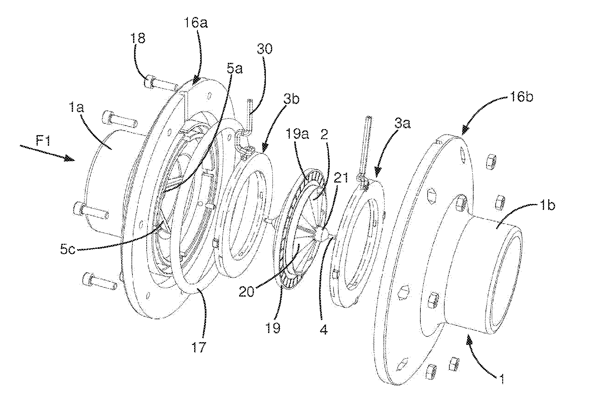
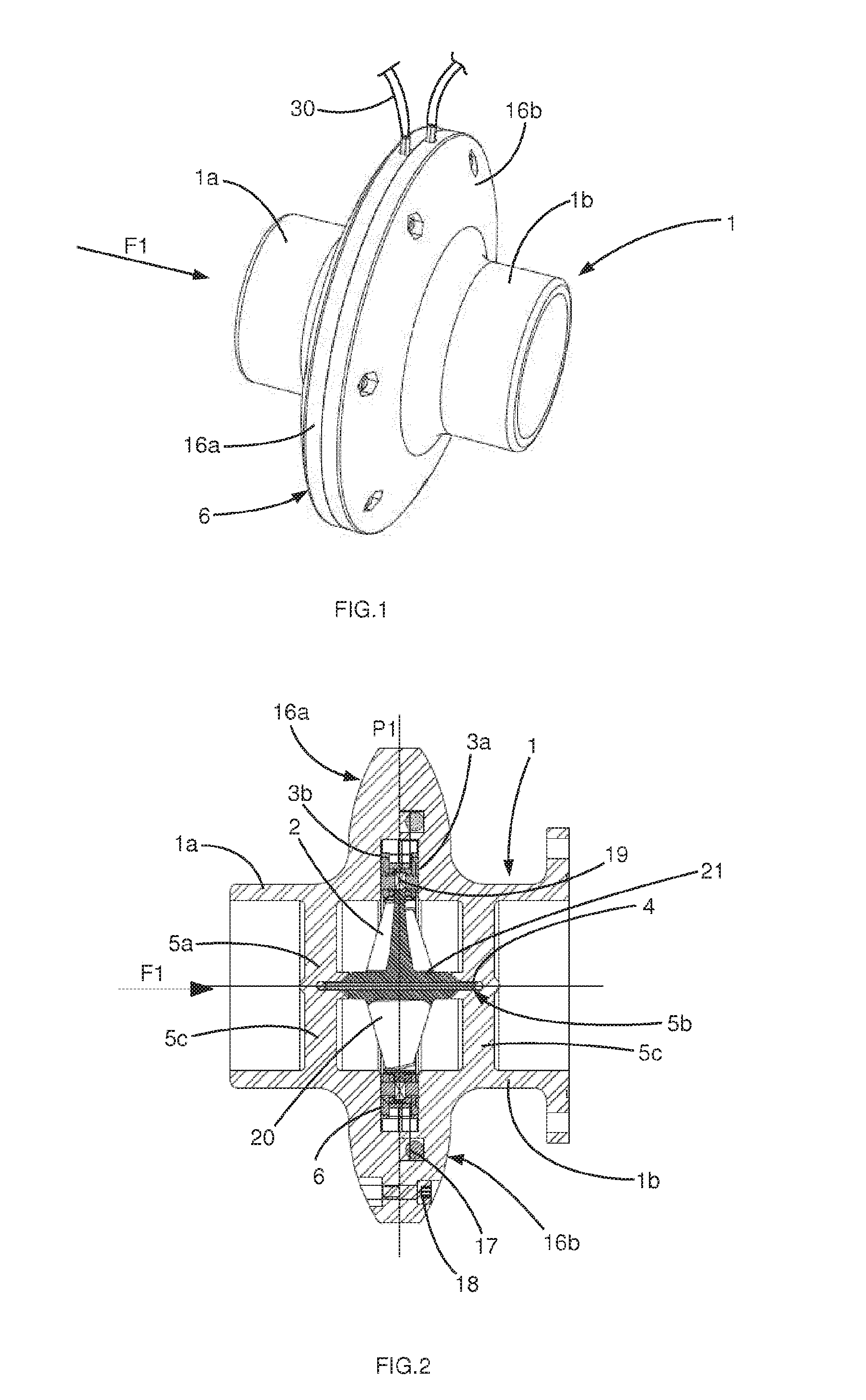
The device for generating an electrical current, intended for a pipeline includes a pipe element (1), a rotor (2) suitable for being set in motion by the fluid and a stator (3a, 3b) arranged to cooperate with an end of the rotor (2) opposite to an axis of rotation (4) of said rotor (2) in order to generate the electrical current. The axis of rotation (4) is mounted at its opposing longitudinal ends (4a, 4b) on first and second supports (5a, 5b) arranged on either side of the plane of rotation (P1) of the rotor (2) and each linked to the pipe element (1). The stator has at least one ring (3a) arranged on one side of the rotor (2), and each ring (3a, 3b) includes a circuit suitable for generating all or part of the electrical current when excited by a magnetic element of the rotor (2).

Description

TECHNICAL FIELD OF THE INVENTION[0001]The invention relates to the field of current generation, notably from the flow of a fluid in a duct or a pipeline.[0002]The subject of the invention is, more particularly, a device for generating an electrical current, said device being intended to form a part of a pipeline for circulation of a fluid, notably liquid.[0003]Another object according to the invention relates to a kit making it possible to use a pipeline with an electrical current generation device.[0004]Yet another object of the invention relates to an installation provided with a pipeline for circulation of a fluid in which the fluid circulates, said pipeline comprising at least one device for generating electrical current from the circulation of the fluid within the pipeline.STATE OF THE ART[0005]In the field of electricity generated from renewable energies such as water, it is common practice to channel the water from a dam in a large duct several metres in diameter in order to ...

Claims


Application Information

Patent Timeline
IPC IPC(8): H02K7/18H02K3/04F03B13/10H02K5/20H02K9/00H02K1/06H02K5/12
CPCF03B3/04F03B13/10H02K7/1823F05B2220/20F05B2220/7068H02K9/00Y02E10/22H02K1/06H02K3/04H02K5/12H02K5/20Y02E10/223Y02E10/20H02K5/203
Inventor PERRIERE, BERNARD
Owner SAVE INNOVATIONS
Why Eureka
Try Eureka