Biological information measurement system
a biochemical information and measurement system technology, applied in the field of biochemical information measurement system, can solve the problem of no effective device other than diagnosis at hospital for checking, and achieve the effect of accurate recognition, increased cancer risk, and simplified knowledg
- Summary
- Abstract
- Description
- Claims
- Application Information
AI Technical Summary
Benefits of technology
Problems solved by technology
Method used
Image
Examples
first embodiment
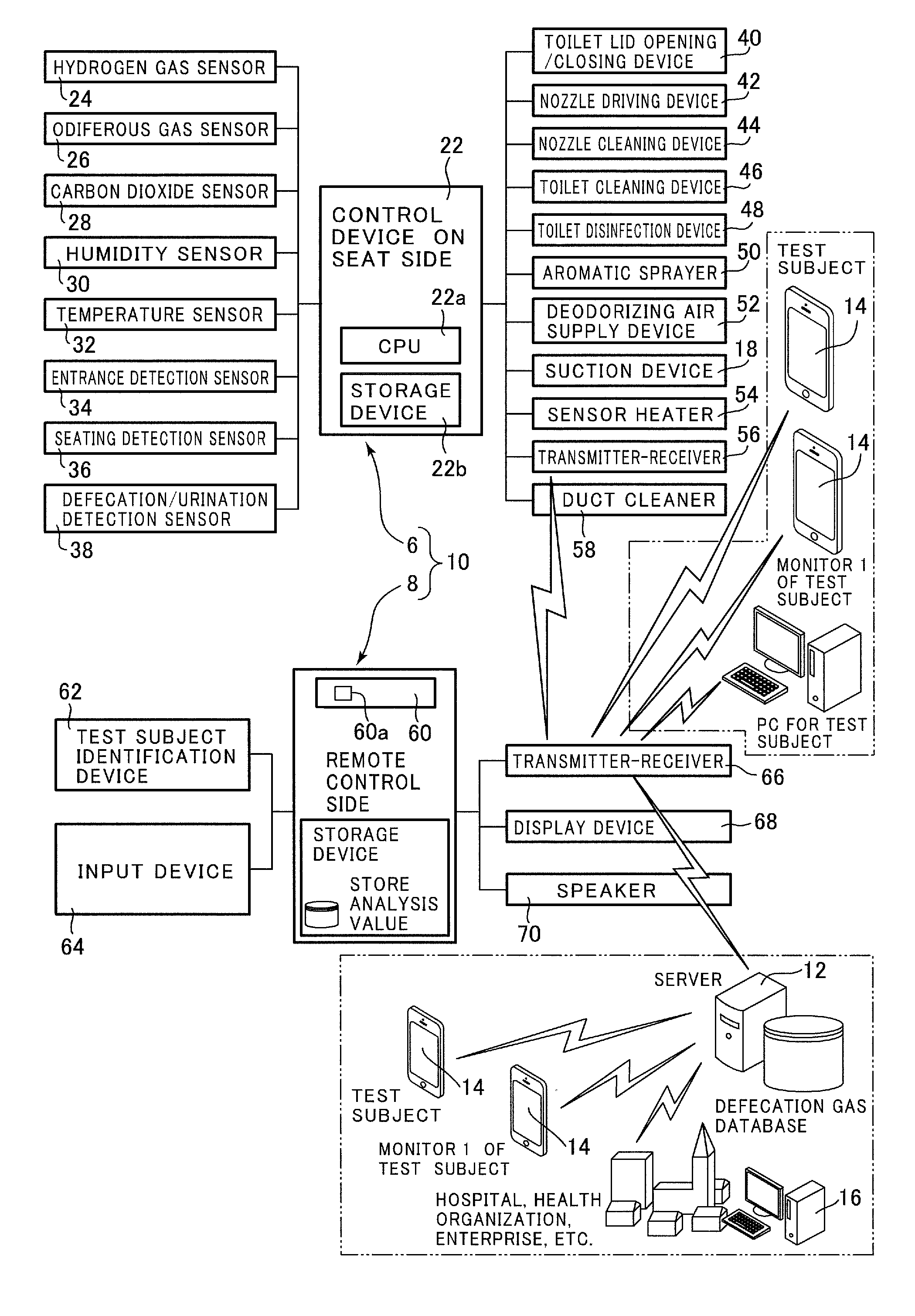
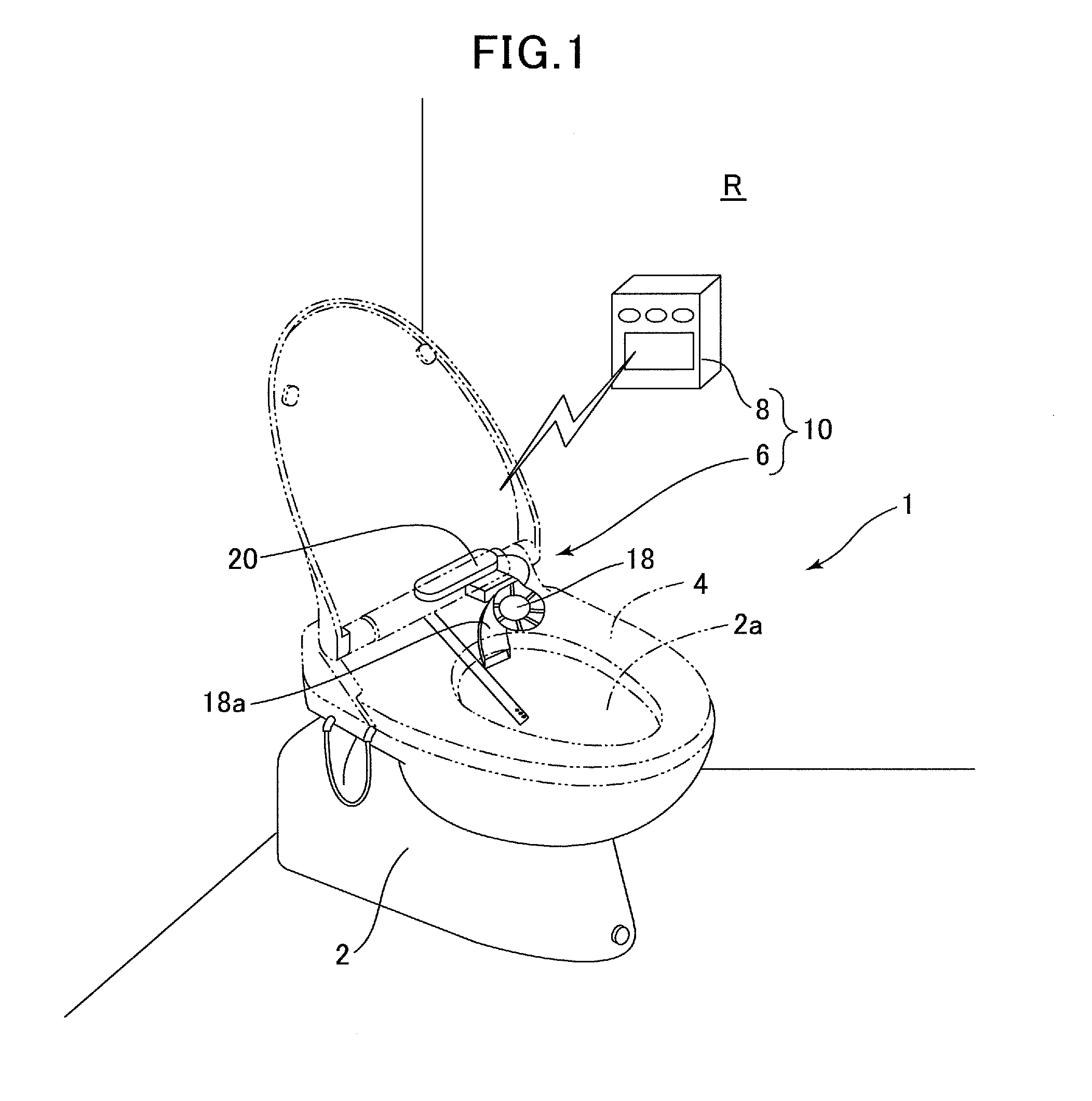
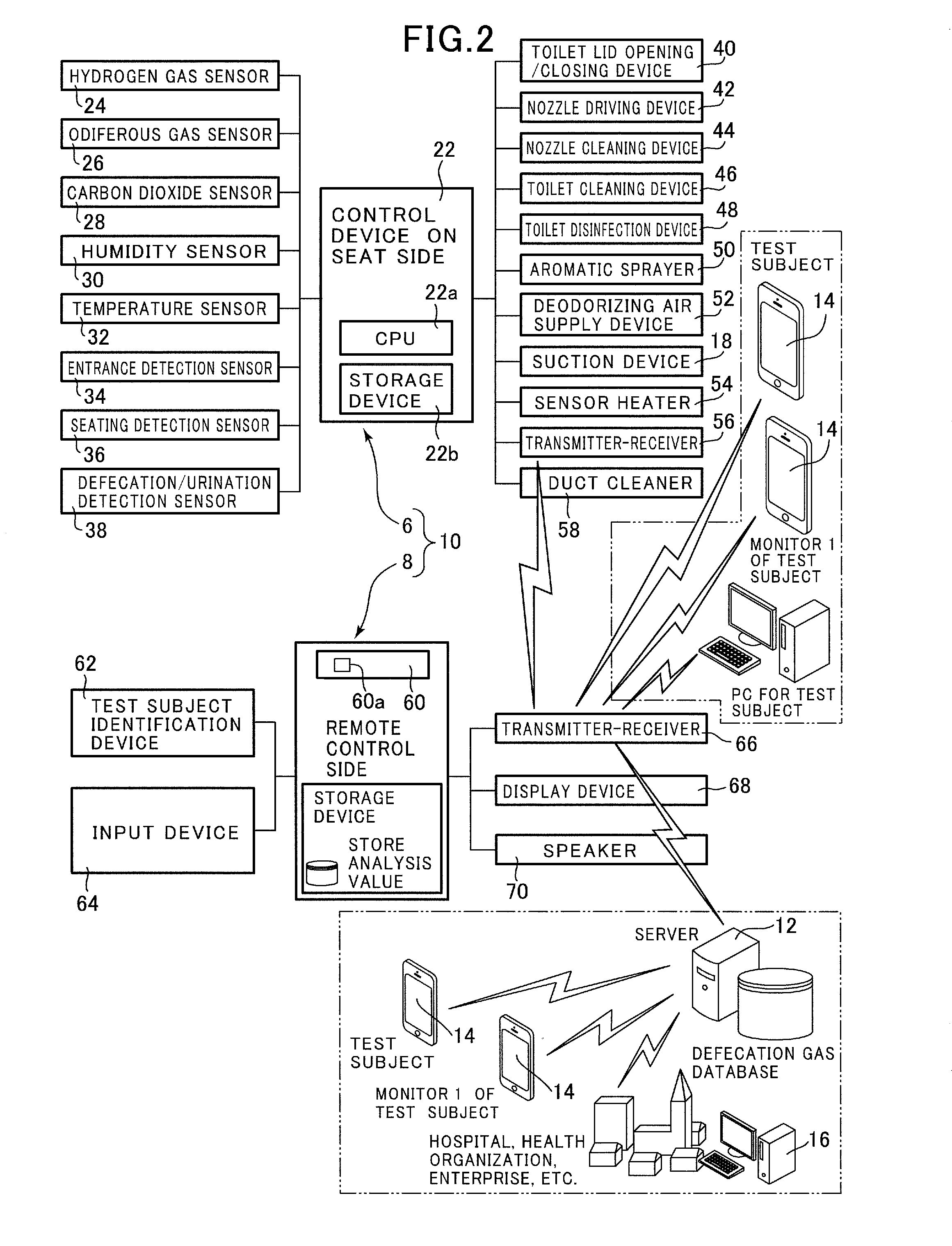
[0121]FIG. 1 shows a state in which a biological information measurement system in accordance with the present invention is attached to a flush toilet installed in a toilet installation room. FIG. 2 is a block diagram showing a configuration of the biological information measurement system of the present embodiment. FIG. 3 shows a configuration of gas detector provided in the biological information measurement system of the present embodiment.
[0122]As shown in FIG. 1, the biological information measurement system 1 includes a measuring device 6 assembled inside a seat 4 mounted on a flush toilet 2 installed in a toilet installation room R, and a device 10 on a test subject side composed of a remote control 8 attached to a wall surface of the toilet installation room R. In addition, as shown in FIG. 2, the biological information measurement system 1 includes a server 12, a terminal 14 for a test subject, formed by installing dedicated software in a smartphone, and the like, and a med...
seventh embodiment
[0364]Next, with reference to FIG. 41, a biological information measurement system according to the present invention will be described.
[0365]In the aforementioned first embodiment, a plotted point representing physical condition is displayed in the physical condition display table, on the basis of the detection data of odiferous gas and hydrogen gas which are detected. The present embodiment differs from the aforementioned first embodiment only in that a position of a plotted point displayed in the physical condition display table is corrected on the basis of the detection data of carbon dioxide gas. Accordingly, only the point of the present embodiment differing from the first embodiment will be described, and explanation of the same components and the like will be omitted.
[0366]FIG. 41A shows an example of correction of a plotted point displayed in a physical condition display table. FIG. 41B shows an example of an amount of correction based on an amount of carbon dioxide gas whi...
eighth embodiment
[0377]Next, with reference to FIG. 43, a biological information measurement system according to the present invention will be described.
[0378]The present embodiment differs from the aforementioned first embodiment only in that the aforementioned first embodiment displays the plotted points based on the detection data of about last thirty days are displayed in the physical condition display table, whereas the present embodiment has a physical condition display table that displays analysis results of a long previous period. Accordingly, only difference of the present embodiment from the first embodiment will be described here, and explanation of the similar components and the like will be omitted.
[0379]As shown in FIG. 43, in the present embodiment, the previous analysis results are plotted in the physical condition display table as a plurality of historical representative values collectively at each predetermined period. That is, in the present embodiment, a point of a center of an a...
PUM
| Property | Measurement | Unit |
|---|---|---|
| temperature | aaaaa | aaaaa |
| temperature | aaaaa | aaaaa |
| physical condition | aaaaa | aaaaa |
Abstract
Description
Claims
Application Information
 - R&D
- Intellectual Property
- Life Sciences
- Materials
- Tech Scout
- Unparalleled Data Quality
- Higher Quality Content
- 60% Fewer Hallucinations
Browse by: Latest US Patents, China's latest patents, Technical Efficacy Thesaurus, Application Domain, Technology Topic, Popular Technical Reports.
© 2025 PatSnap. All rights reserved.Legal|Privacy policy|Modern Slavery Act Transparency Statement|Sitemap|About US| Contact US: help@patsnap.com


