Rotating rapid-firing defense weapon system

a defense weapon system and rapid-fire technology, applied in the field of surface-to-air defense weapon systems, can solve problems such as falling debris

Inactive Publication Date: 2016-08-04
LEWIS NATHANIAL HENRY
View PDF0 Cites 2 Cited by
  • Summary
  • Abstract
  • Description
  • Claims
  • Application Information

AI Technical Summary

Problems solved by technology

The ships are out at sea and are moving; falling debris is o...

Method used


Image

  • Rotating rapid-firing defense weapon system
  • Rotating rapid-firing defense weapon system
  • Rotating rapid-firing defense weapon system

Examples


Embodiment Construction

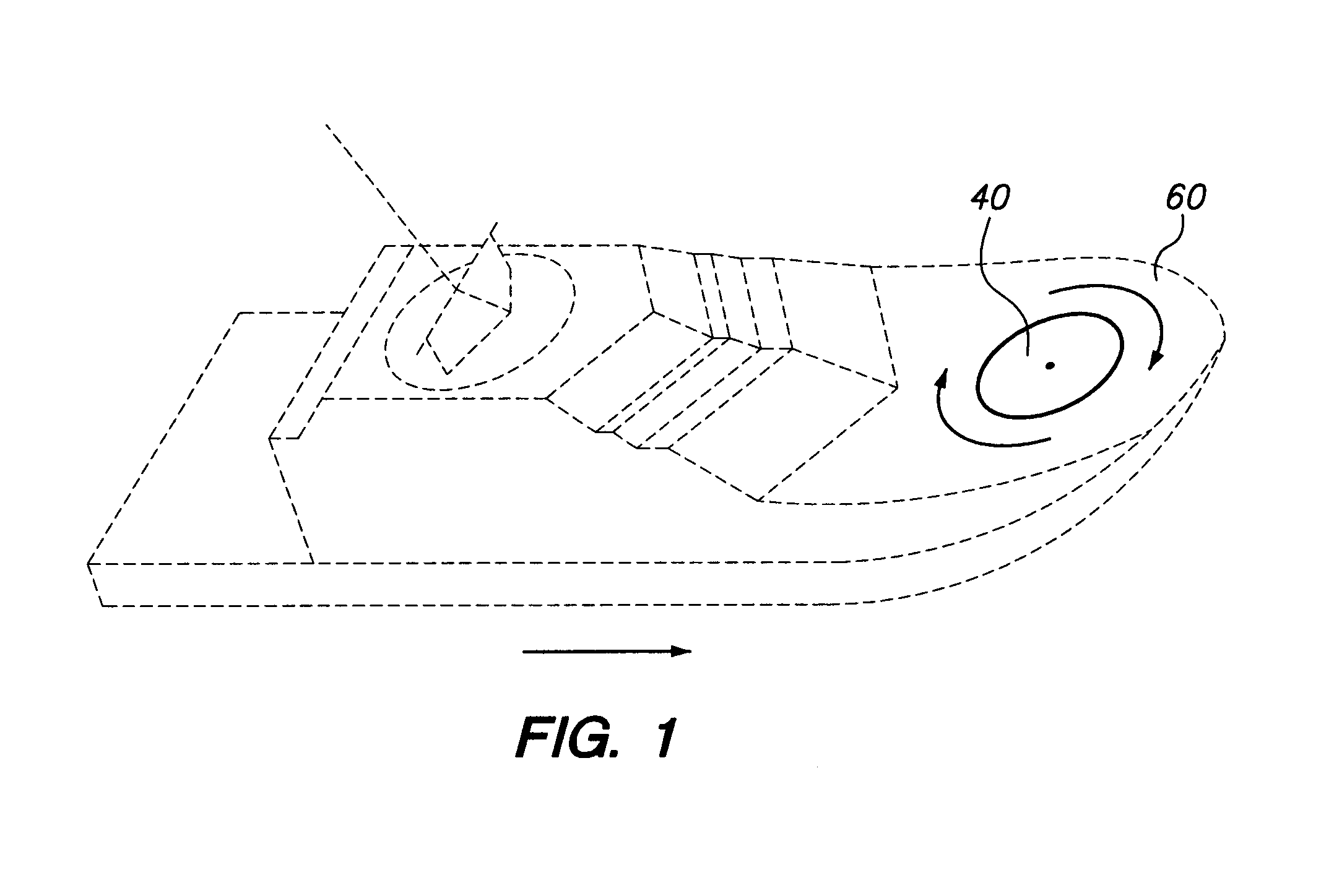
[0020]FIG. 1 shows a good place to place this system. The rotating circular platform 40 is placed on a ship's forward deck 60, or on a land based structure. The ship can be modified existing one or a new one. The ship can have its own ballistic missiles detection ability or rely on other ships of a Navy battle group for detection of incoming ballistic missiles.

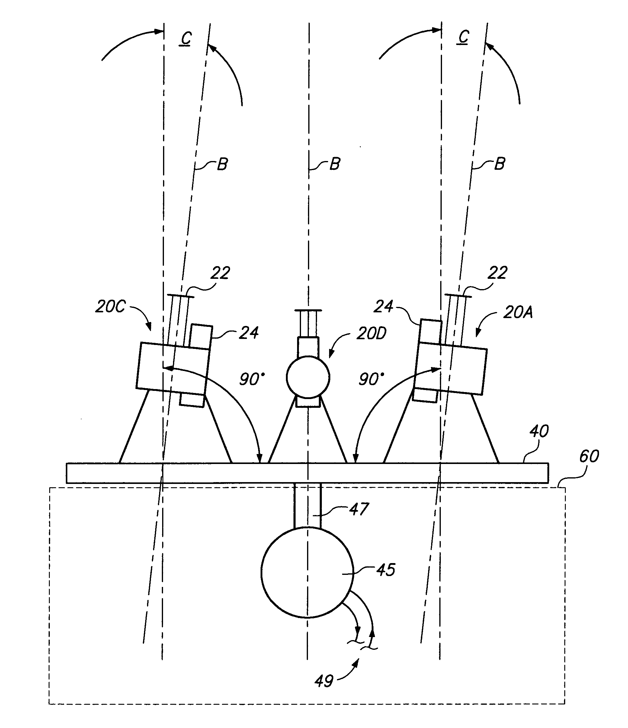
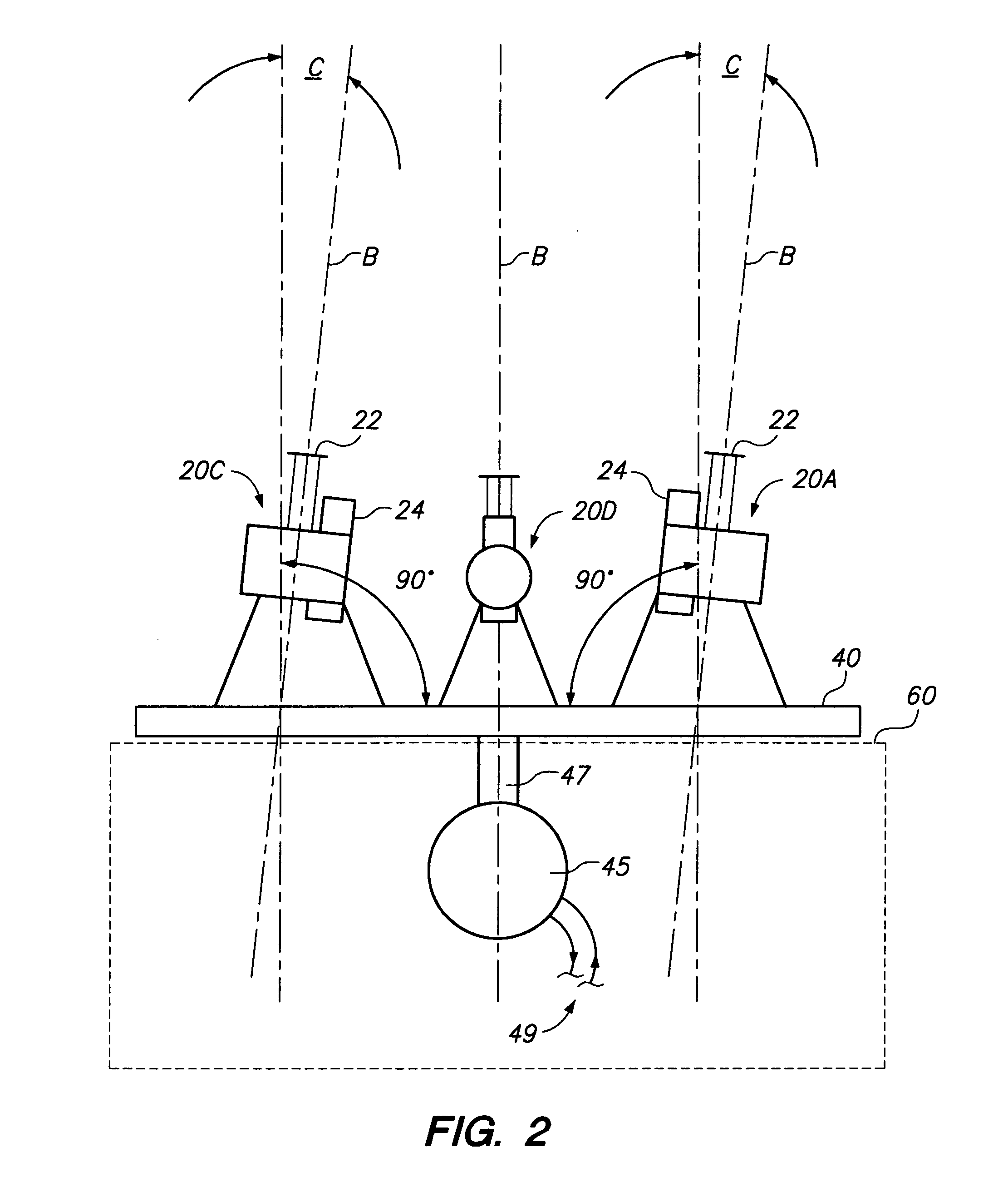
[0021]FIG. 2 shows a powerful electric motor 45 and its electrical connection 49 under the deck 60, the platform 40 is rotated with the motor's shaft 47. On the platform 40 is mounted four modified guns. Many types of modified guns can be used from a single barrel to a multiple barrel. Each of these guns 20A, 20B, 20C and 20D comprises an inner regulated power supply section, equipment protection section fire-control mechanisms and outer multiple barrels 22 and an ammunition drum 24; gun 20B is omitted for clarity. The equipment support column 55 and electrical connections are omitted for clarity.

[0022]The stationary guns 20A ...


PUM


Abstract

Guns are fired simultaneously from a rotating platform. This is primarily a last-ditch, defense weapon system to protect the Navy's aircraft carriers and the Marine Corps amphibious landings: This system would have the ability to destroy all of many incoming ballistic missiles and bombs, and their fragmentation over a wide area. The ships are out at sea and are moving; falling debris is only a minor problem compared to getting hit by a bomb or missile. A land or port version of this system may be of some interest; such as a system on a mobile water platform or vehicle. The system could certainly knock down a swarm of hostile unmanned aerial vehicles.

Description

BACKGROUND OF THE INVENTION[0001]1. Field of the Invention[0002]The present system relates to the field of the U.S. Navy's weapon systems. Specifically, it relates to a surface-to-air defense weapon system. This system will be used primarily to protect the Navy's aircraft carriers. It would have the ability to destroy all of many incoming ballistic missiles and bombs, and their fragmentation over a wide area.[0003]2. Description of the Related Art[0004]Any discussion of the prior art throughout the specification should in no way be considered as an admission that such prior art is widely known or forms part of common general knowledge in the field.[0005]The monthly magazine Seapower is about the Navy, Marine Corps, Coast Guard and Merchant Marine. It is a sea services directory that gives the latest information on all weapons and many other things as well. It will be the subject of ships' surface-to-air weapons that I am concerned with for this system, the defense against ballistic ...

Claims


Application Information

Patent Timeline
IPC IPC(8): F41H11/02F41G5/20
CPCF41G5/20F41H11/02F41G3/165F41G3/22F41G5/06F41G3/04F41H11/04F41A23/24F41A27/04F41A27/14F41A27/16F41A27/20F41F1/085
Inventor LEWIS, NATHANIAL HENRY
Owner LEWIS NATHANIAL HENRY
Why Eureka
Try Eureka