
Device and method of phase-locking brain stimulation to electroencephalographic rhythms

Inactive Publication Date: 2016-08-04
THE BOARD OF TRUSTEES OF THE UNIV OF ARKANSAS
View PDF10 Cites 59 Cited by
  • Summary
  • Abstract
  • Description
  • Claims
  • Application Information

AI Technical Summary

Benefits of technology

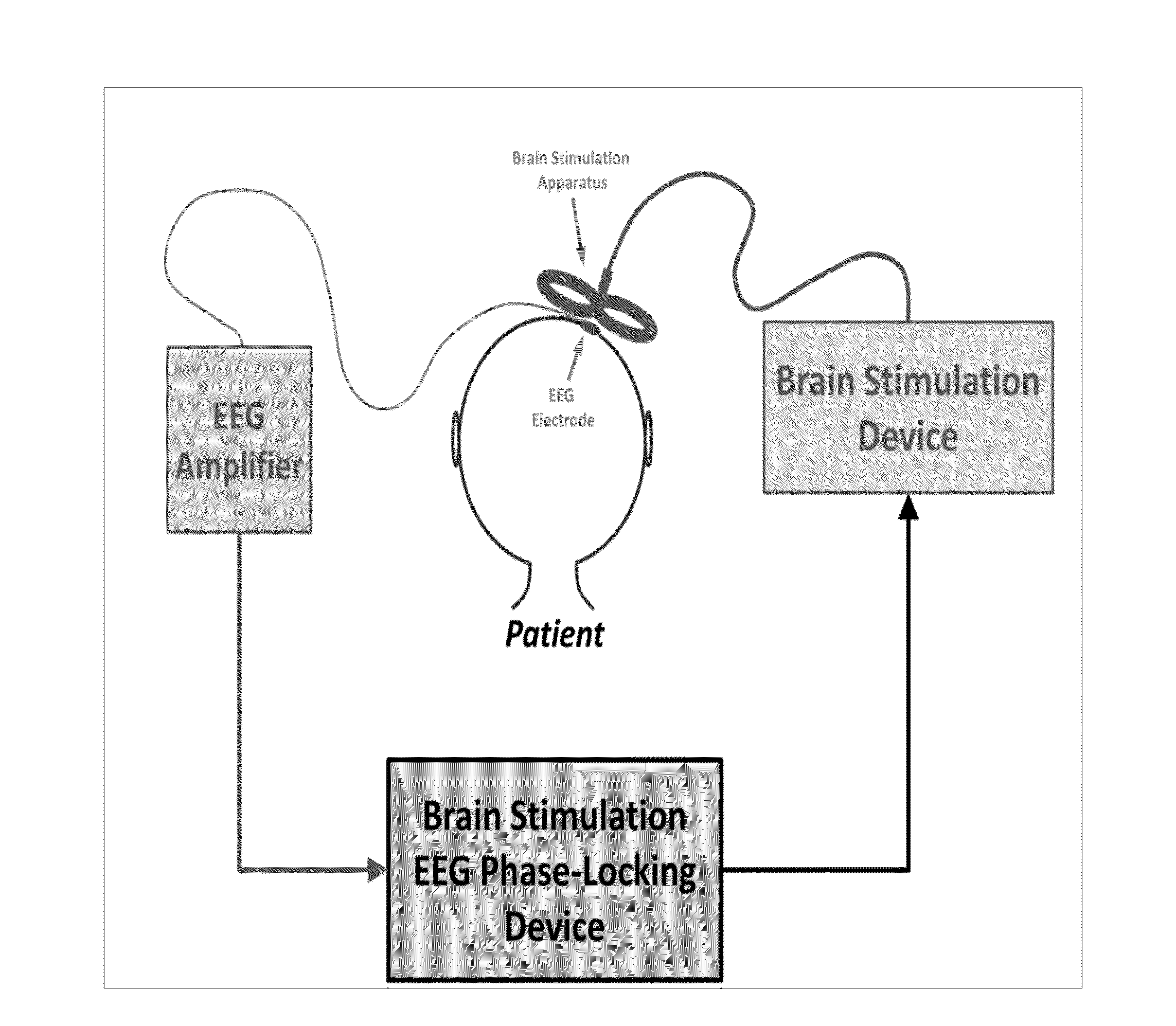
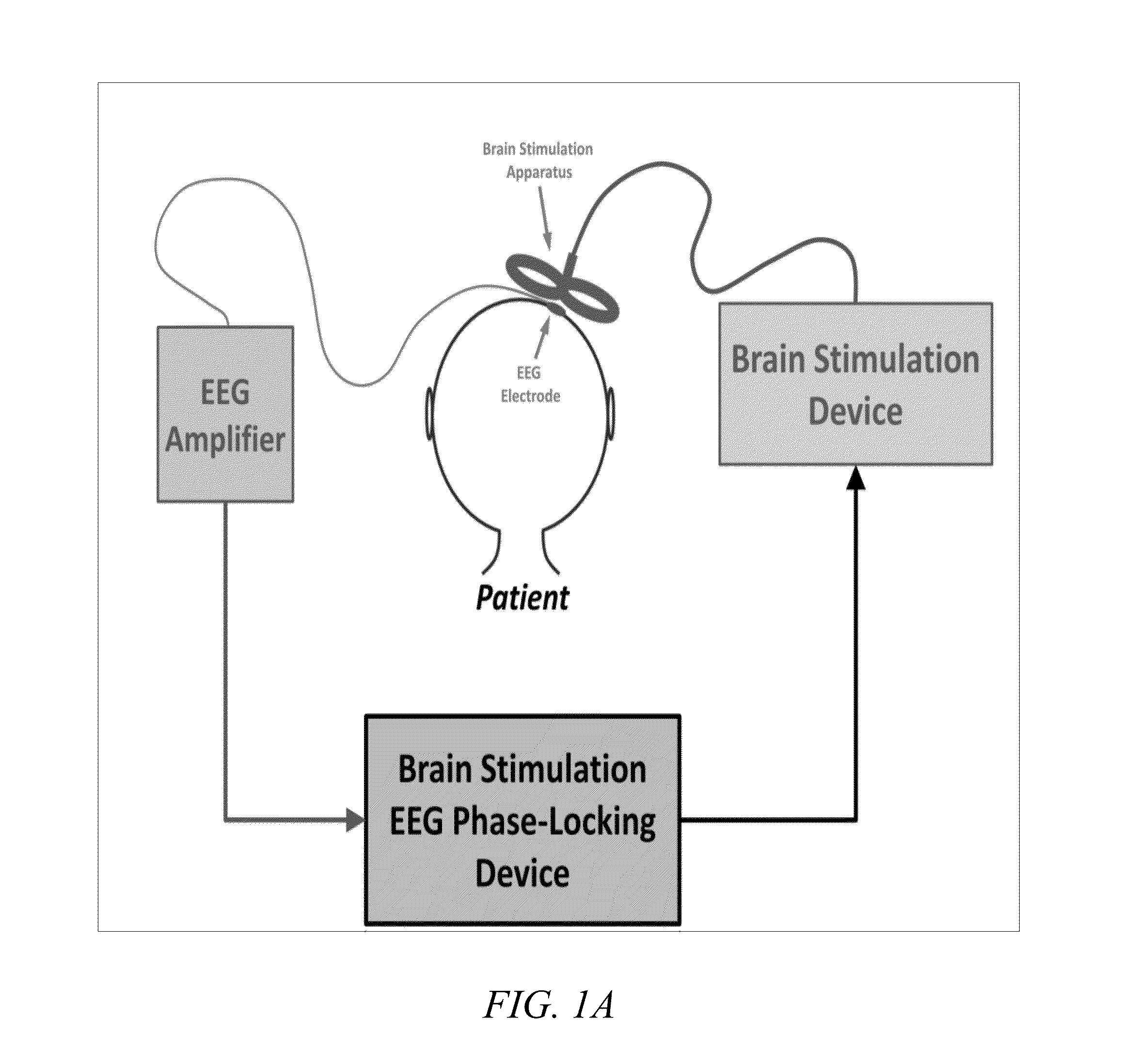
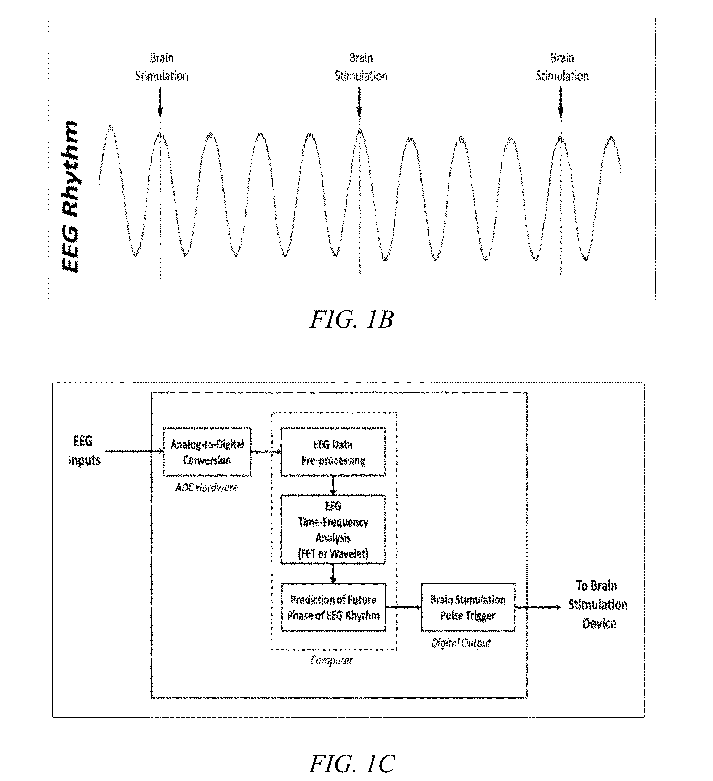
The invention is a device and system for brain stimulation that is synchronized with electroencephalographic rhythms. The device includes an electroencephalogram input and a brain stimulation pulse trigger output. The system includes an electroencephalogram-gated, transcranial magnetic stimulation device that provides a timed brain stimulation pulse to a transcranial magnetic stimulation coil in synchrony with a predetermined phase of an endogenous brain rhythm as measured by an electroencephalogram. The system also includes an analysis unit that performs real-time or near real-time signal analysis of the endogenous brain rhythm and extracts frequency-domain phase information to estimate a predicted electroencephalogram rhythm phase, which is then used to trigger the brain stimulation pulse. The method includes acquiring an endogenous brain rhythm signal, performing real-time or near real-time signal analysis, extracting frequency-domain phase information, and triggering a brain stimulation pulse in alignment with the predicted electroencephalogram rhythm phase. The technical effects of the invention include improved brain stimulation synchronization with electroencephalographic rhythms, improved brain stimulation effectiveness, and improved brain stimulation safety.

Problems solved by technology

Though therapeutic uses of brain stimulation are expanding, improvements in the efficacy of these techniques have remained relatively stagnant over the past decade.
A major limitation of these current brain stimulation therapies, however, is that they are all administered without regard to the natural, continuous, and ongoing fluctuations in the activity of a patient's brain.

Method used


Image

  • Device and method of phase-locking brain stimulation to electroencephalographic rhythms
  • Device and method of phase-locking brain stimulation to electroencephalographic rhythms
  • Device and method of phase-locking brain stimulation to electroencephalographic rhythms

Examples


example 1

[0060]For Example 1, pilot data (N=4) was collected from peak burst, trough burst, and conventional iTBS sessions. MEP and TEP data for pre-rTMS and one post-rTMS time point directly following rTMS administration (equivalent to the pre-rTMS and 10-minute post-rTMS measures of MEPs and TEPs) was collected, and plots of time-domain averages of EEG activity within a short time window leading up to a 50 Hz burst of TMS pulses are illustrated in FIG. 4, plotted separately for peak burst and trough burst conditions. Example 1 shows the intended phase differences and temporal alignment for these two rTMS stimulation protocols. The 50-Hz burst of three pulses onset at an average phase of 16.8° for peak burst and 159.4° for trough burst. The data from Example 1 demonstrates the feasibility and effectiveness of the device and method disclosed herein for time-locking to a desired alpha phase. Percent modulation of MEPs for peak burst, trough burst, and conventional iTBS is presented in FIG. 5,...

example 2

[0061]Example 2 addresses alpha phase and excitatory rTMS in order to determine the relationship between alpha phase and TMS-induced excitation in the human cortex. Alpha oscillations reflect cycles of inhibition in cortex, and as such, the instantaneous phase of alpha reflects the present state of excitability in cortex as it relates to the naturally occurring synchronous networks reflected in alpha. As a subpopulation of neurons within cortex is expected to be synchronously activated (or deactivated) according to alpha phase, inducing a state of neuroplasticity with TMS at a particular phase in order to provide a method of enhancing LTP within a target population of cells and / or modulating inter-regional communication. Alpha phase-related effects of TMS-induced excitability are examined by time-locking high-frequency bursts of TMS to peaks or troughs of alpha phase and comparing pre- and post-measures of cortical excitability from MEPs, TEPs, and ERPs. Example 2 compares the magni...

example 3

[0070]Example 3 addressed alpha phase and inhibitory rTMS (1 Hz) and determined the relationship between alpha phase and TMS-induced inhibition in the human cortex. Inhibitory effects on cortical excitability induced in the human brain by 1-Hz rTMS result from NMDA-dependent mechanisms of LTD. Like LTP, the induction of LTD is also activity dependent, requiring suprathreshold levels of low-frequency stimulation. Thus, the inhibitory effects of 1-Hz rTMS would also be expected to interact with the level of synchronized cortical excitability, just as high-frequency would. Example 3 examined this possibility by administering a 1-Hz inhibitory rTMS protocol with TMS pulses time-locked to specific phases of the alpha rhythm (peak or trough). As in Example 2, Example 3 compares the efficacy of alpha phase-locked 1-Hz rTMS to a standard 1-Hz rTMS protocol and a sham stimulation session.

[0071]Procedure.

[0072]The procedure of Example 3 was identical to that of Example 2 above 1 with the exce...


PUM


Abstract

The device and method for phase-locking brain stimulation to electroencephalographic rhythms improves the accuracy, specificity, and effectiveness of non-invasive brain stimulation devices by timing pulses of brain stimulation to occur in synchrony with naturally occurring brain rhythms measured at the scalp of a patient in order to treat an assortment of neurological and psychiatric conditions. The device and method provided herein improve non-invasive brain stimulation techniques by time-locking the onset of brain stimulation to the phase of naturally-occurring rhythmic oscillations of brain activity that can be recorded with electroencephalography (EEG). The device and method perform real-time signal analysis of a specified EEG rhythm, extract frequency-domain phase information to estimate the next occurrence of a desired EEG rhythm phase, and trigger a brain stimulation pulse so as to align precisely with this predicted EEG phase.

Description

CROSS REFERENCE TO RELATED APPLICATIONS[0001]This application claims the benefit of and priority to U.S. Provisional Patent Application Ser. No. 62 / 109,982, filed Jan. 30, 2015, which is incorporated herein by reference in its entirety.STATEMENT REGARDING FEDERALLY SPONSORED RESEARCH OR DEVELOPMENT[0002]Not Applicable.NAMES OF THE PARTIES TO A JOINT RESEARCH AGREEMENT[0003]Not Applicable.REFERENCE TO A SEQUENCE LISTING, A TABLE, OR A COMPUTER PROGRAM LISTING APPENDIX[0004]Not Applicable.STATEMENT REGARDING PRIOR DISCLOSURES BY THE INVENTOR OR A JOINT INVENTOR[0005]Not Applicable.BACKGROUND OF THE INVENTION[0006]1. Field of the Invention[0007]This invention relates generally to a device and method of phase-locking brain stimulation to electroencephalographic rhythms, and more particularly to a device and method that utilize real-time EEG analysis to measure a patient's brain state, and determine the most opportune time points at which to administer brain stimulation for maximum thera...

Claims


Application Information

Patent Timeline
IPC IPC(8): A61N2/00A61B5/04A61N2/02A61B5/0476A61N1/20A61N1/36
CPCA61N2/006A61N1/20A61B5/04012A61N2/02A61B5/0476A61N1/36025A61N1/36021A61N1/0456A61B5/316A61B5/369A61B5/374
Inventor PARKS, NATHAN ALLEN
Owner THE BOARD OF TRUSTEES OF THE UNIV OF ARKANSAS
Learn More