
Surgical visualizations systems and displays

a technology applied in the field of visualization system and display, can solve the problems of prolonged recovery time, pain, scarring, and increased risk of infection, and achieve the effect of smooth adjustment of viewing angl

Active Publication Date: 2016-08-04
CAMPLEX
View PDF4 Cites 95 Cited by
  • Summary
  • Abstract
  • Description
  • Claims
  • Application Information

AI Technical Summary

Benefits of technology

The patent is about a device that allows a user to view an image from a small camera on a larger display. The device has a special optical system that reduces stray light and directs the light from the camera to the display. The device also has a gimbal that can adjust the viewing angle of the camera between two positions. The device can be used in a medical setting with a camera arm attached to it. The technical effects of this device are improved image quality and greater control over the viewing angle in a compact and easy-to-use device.

Problems solved by technology

Open surgery is associated with significant drawbacks, however, as the relatively large incisions result in pain, scarring, and the risk of infection as well as extended recovery time.
However, because of the small access opening, the surgeon's view and workspace of the surgical site is limited.

Method used


Image

  • Surgical visualizations systems and displays
  • Surgical visualizations systems and displays
  • Surgical visualizations systems and displays

Examples


embodiment

General Embodiment

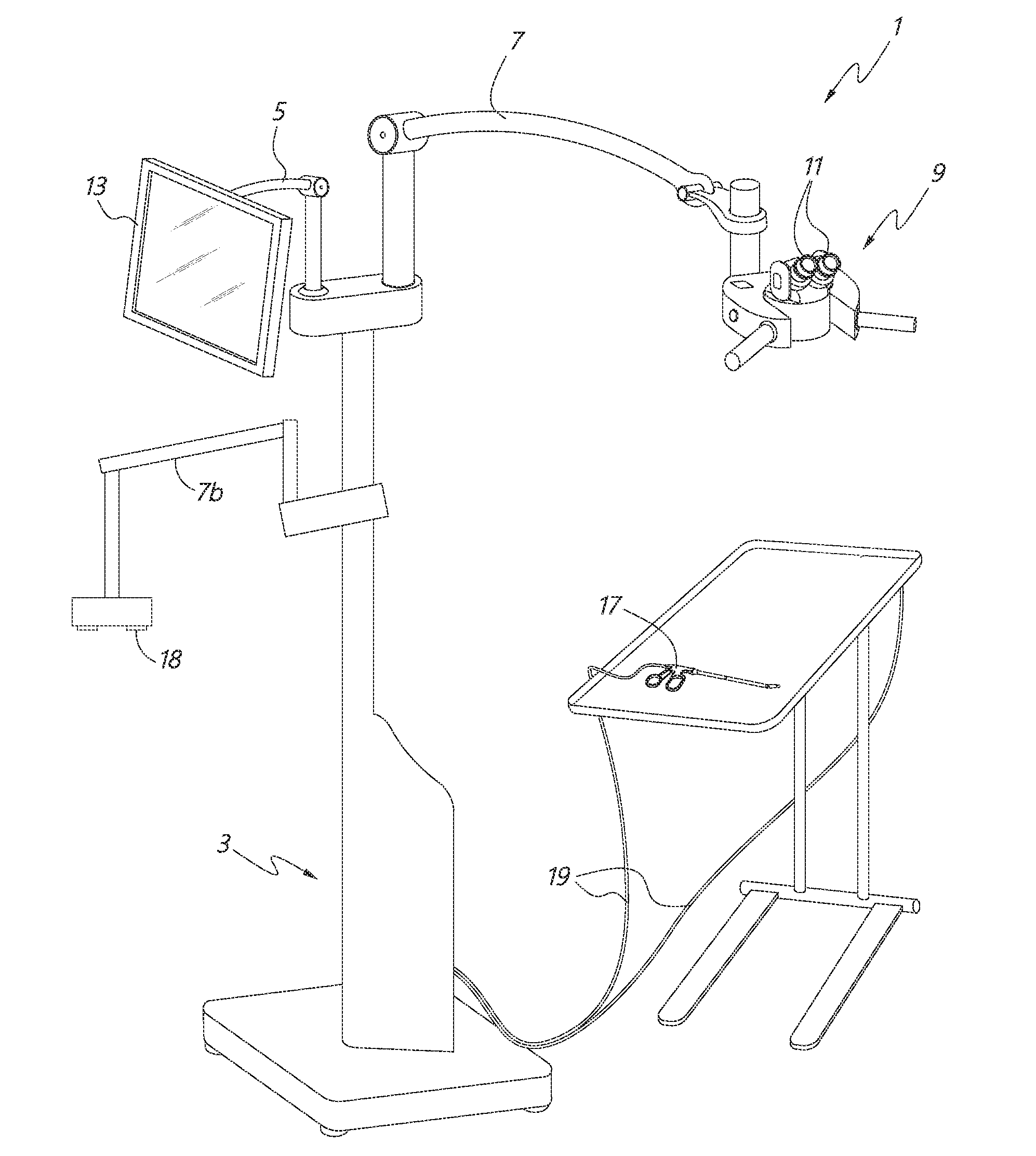
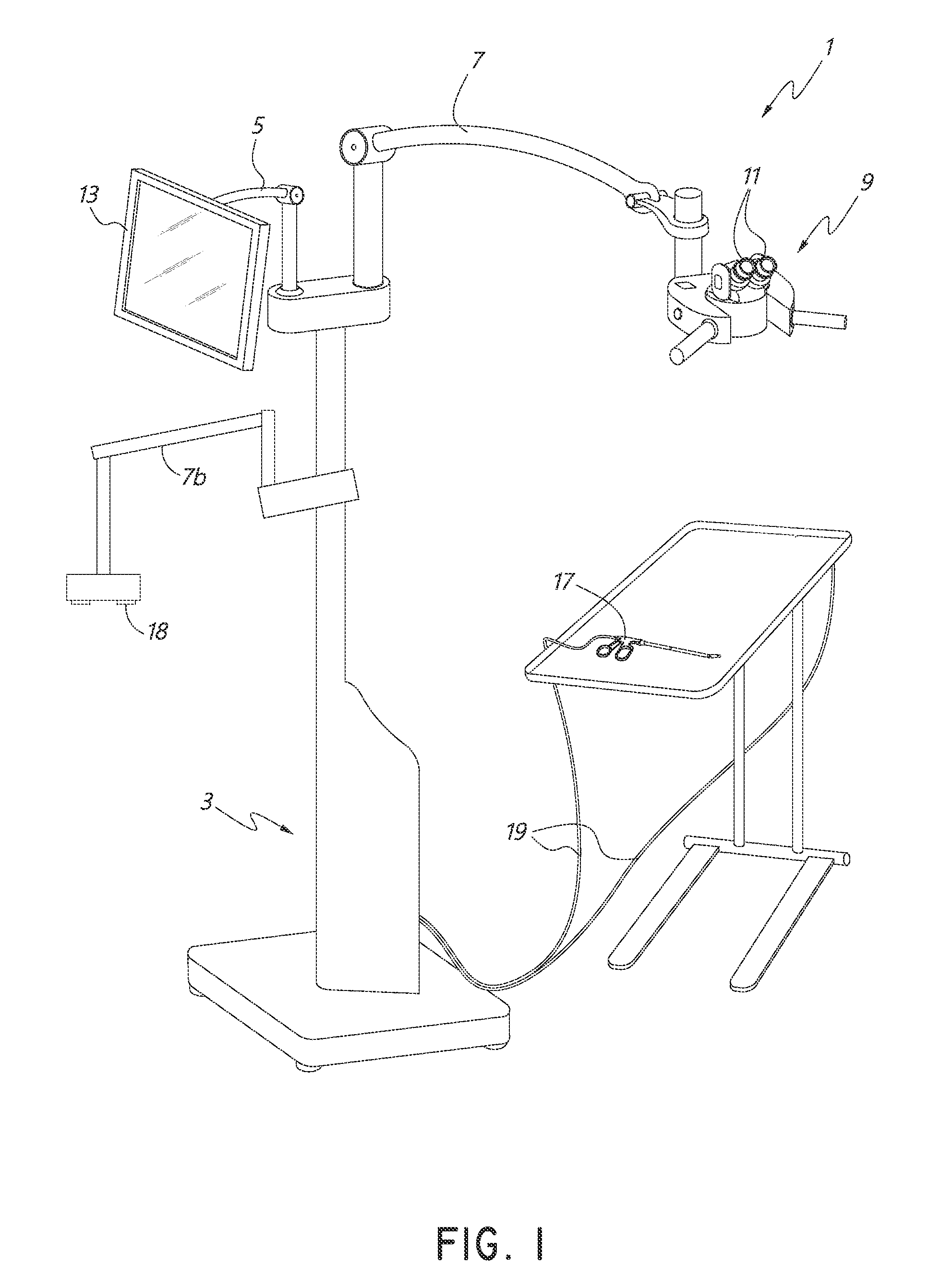
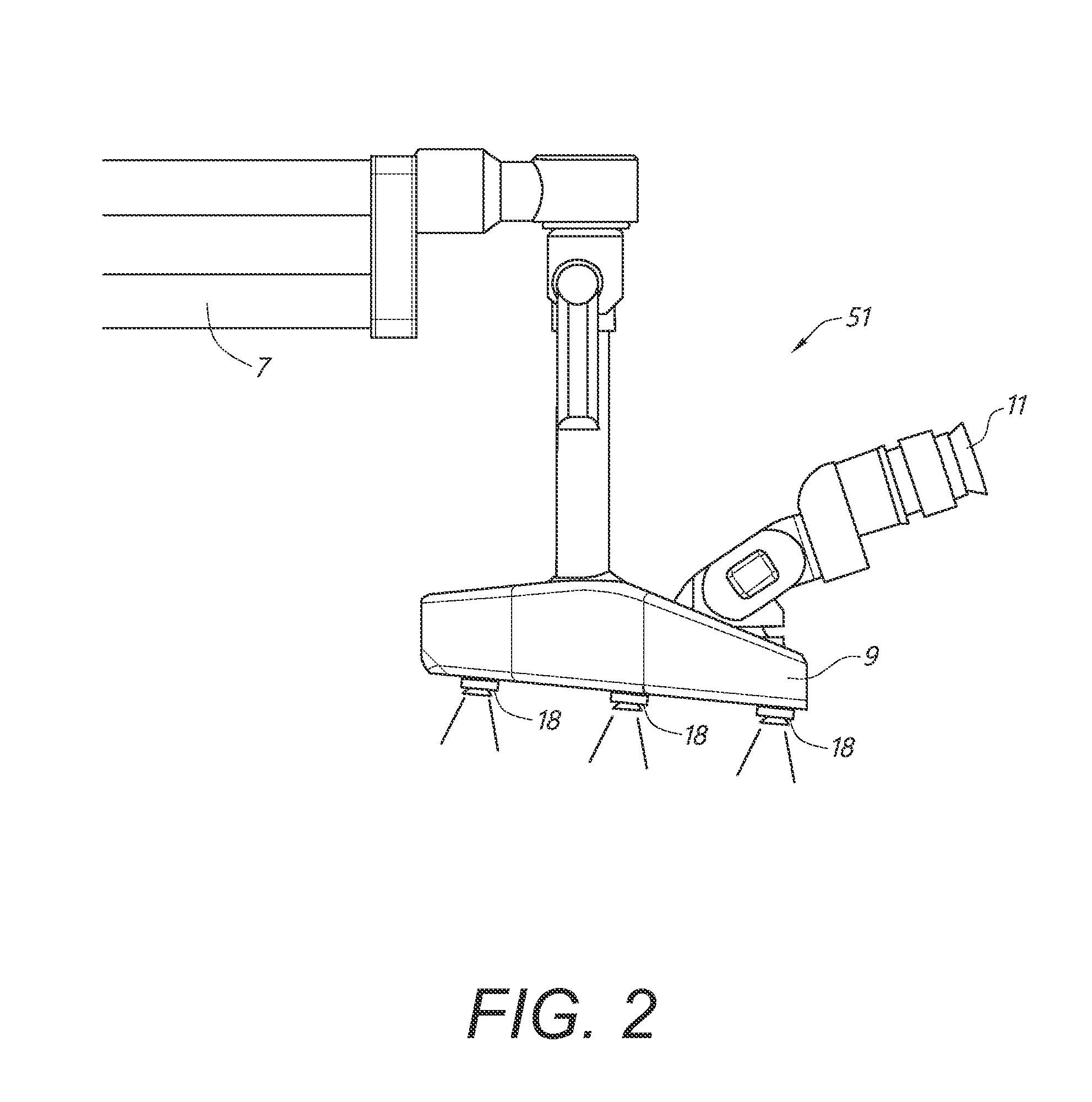
[0159]With continued reference to FIGS. 6A and 6B, in some embodiments, the movement control system 10100 can be attached to an attachment structure, such as binocular display unit 9, and support one or more imagers 18. As shown in the illustrated embodiment, the movement control system 10100 can be oriented generally underneath the binocular display unit 9 and in some embodiments can be sized such that the movement control system 10100 does not extend significantly beyond the outer housing of the binocular display unit 9. This can advantageously provide a smaller form factor thereby reducing the likelihood that the movement control system 10100 will interfere with the medical professionals and assistants during a medical procedure. In other embodiments, the attachment structure can be other components of the surgical visualization system 1 such as, but not limited to, a dedicated articulating arm or a display arm. In some embodiments, the movement control system 1...


PUM


Abstract

A medical apparatus is described for providing visualization of a surgical site. The medical apparatus includes an electronic display disposed within a display housing. The medical apparatus includes a display optical system disposed within the display housing, the display optical system comprising a plurality of lens elements disposed along an optical path. The display optical system is configured to receive images from the electronic display. The medical apparatus can include proximal cameras mounted on a frame, the cameras configured to provide a view of a surgical site from outside the surgical site. The display housing can have a height that is larger than its depth.

Description

CROSS-REFERENCE TO RELATED APPLICATIONS[0001]This application claims the benefit of priority to U.S. Provisional Application No. 62 / 088,470, entitled “SURGICAL VISUALIZATION SYSTEMS AND DISPLAYS,” filed Dec. 5, 2014, to U.S. Provisional Application No. 62 / 098,297, entitled “SURGICAL VISUALIZATION SYSTEMS AND DISPLAYS,” filed Dec. 30, 2014, to U.S. Provisional Application No. 62 / 099,422, entitled “SURGICAL VISUALIZATION SYSTEMS AND DISPLAYS,” filed Jan. 2, 2015, and to U.S. Provisional Application No. 62 / 260,220, entitled “SURGICAL VISUALIZATION SYSTEMS AND DISPLAYS,” filed Nov. 25, 2015, to U.S. Provisional Application No. 62 / 183,148, entitled “SURGICAL VISUALIZATION SYSTEMS AND DISPLAYS,” filed Jun. 22, 2015, to U.S. Provisional Application No. 62 / 184,222, entitled “SURGICAL VISUALIZATION SYSTEMS AND DISPLAYS,” filed Jun. 24, 2015, to U.S. Provisional Application No. 62 / 184,838, entitled “SURGICAL VISUALIZATION SYSTEMS AND DISPLAYS,” filed Jun. 25, 2015, and to U.S. Provisional App...

Claims


Application Information

Patent Timeline
Patent Type & Authority Applications(United States)
IPC IPC(8): A61B90/00H04N5/232A61B90/25H04N7/18
CPCG02B21/0012A61B90/361A61B2090/502A61B90/20A61B2090/371A61B2090/365H04N7/183A61B2090/3941A61B90/25A61B2090/373A61B2576/00H04N5/23293A61B2090/3933A61B90/50A61B2034/2048A61B2034/2055H04N23/63
Inventor TESAR, JOHN
Owner CAMPLEX
Learn More