Stalk cutter device and method of use

a cutting device and stalk technology, applied in the field of stalk cutters, can solve the problems of contaminating the stalk, affecting the quality of the stalk, so as to prevent the contamination of the stalk

Active Publication Date: 2016-08-04
THE BOARD OF TRUSTEES OF THE UNIV OF ARKANSAS
View PDF0 Cites 2 Cited by
  • Summary
  • Abstract
  • Description
  • Claims
  • Application Information

AI Technical Summary

Benefits of technology

[0023]In general, in a first aspect, the invention relates to a stalk cutter device for obtaining a desired length of a plant stalk from a desired distance from the ground. The device includes a pair of ergonomic handles pivotally connected to a pair of pruning type cutters at terminal ends of the handles. A support rod is mounted through the pivot connections of the handles and the cutters, and the support rod extends downwardly from one of the cutters the desired distance to the ground. The cutters are axially aligned and coaxially spaced along the rotational axis formed by the support rod, with the cutters configured in a spaced relation for obtaining the desired length of the stalk in a single motion. Moreover, the cutters are configured to retain the stalk and prevent contamination of the stalk while a user obtains the stalk sample.

Problems solved by technology

This method is very cumbersome and generally requires two (2) people to be performed properly and accurately.
When using this current method, there is the potential for several sources of variability to occur especially when making multiple cuts that low to the ground with either hand pruners or machetes.
Therefore, collecting samples properly and efficiently is a major problem and is a primary limiting factor in the widespread adoption of this diagnostic tool.

Method used


Image

  • Stalk cutter device and method of use
  • Stalk cutter device and method of use
  • Stalk cutter device and method of use

Examples


Embodiment Construction

[0036]The devices and methods discussed herein are merely illustrative of specific manners in which to make and use this invention and are not to be interpreted as limiting in scope.

[0037]While the invention has been described with a certain degree of particularity, it is to be noted that many modifications may be made in the details of the construction and the arrangement of the elements and components of the devices and / or in the sequences and steps of the methods without departing from the scope of this disclosure. It is understood that the devices and methods are not limited to the embodiments set forth herein for purposes of exemplification.

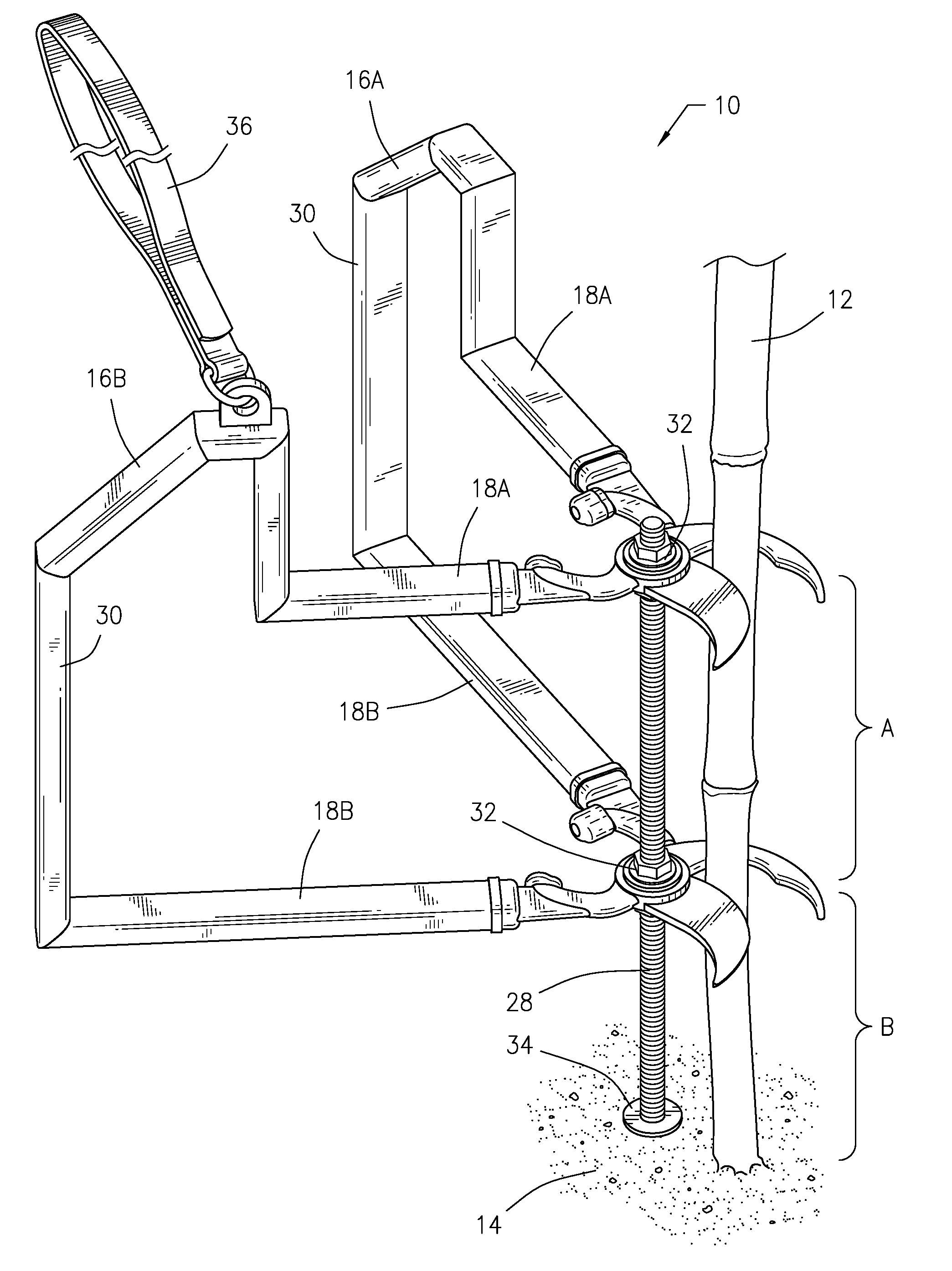
[0038]The description of the invention is intended to be read in connection with the accompanying drawings, which are to be considered part of the entire written description of this invention. In the description, relative terms such as “front,”“rear,”“lower,”“upper,”“horizontal,”“vertical,”“above,”“below,”“up,”“down,”“top” and “bottom” as we...


PUM


Abstract

The stalk cutter device and method of use thereof obtains a desired length of plant stalk, particularly a cornstalk, from a desired distance from the ground. The stalk cutter device includes a pair of handles pivotally connected to a pair of pruning type of cutters. A support rod is mounted through the pivot connections of the cutters and extends laterally a desired distance from the lower cutter to support the device at the desired height to cut the desired portion of the stalk.

Description

CROSS REFERENCE TO RELATED APPLICATIONS[0001]This application claims the benefit of and priority to U.S. Provisional Patent Application Ser. No. 62 / 109,917, filed Jan. 30, 2015, which is incorporated herein by reference in its entirety.STATEMENT REGARDING FEDERALLY SPONSORED RESEARCH OR DEVELOPMENT[0002]Not Applicable.NAMES OF THE PARTIES TO A JOINT RESEARCH AGREEMENT[0003]Not Applicable.REFERENCE TO A SEQUENCE LISTING, A TABLE, OR A COMPUTER PROGRAM LISTING APPENDIX[0004]Not Applicable.STATEMENT REGARDING PRIOR DISCLOSURES BY THE INVENTOR OR A JOINT INVENTOR[0005]Not Applicable.BACKGROUND OF THE INVENTION[0006]1. Field of the Invention[0007]This invention relates generally to a stalk cutter device and method of use thereof, and in particular to a dual, spaced stalk cutter device and method of use for obtaining a desired length of plant stalk, particularly a cornstalk, from a desired distance from the ground.[0008]2. Description of the Related Art.[0009]Currently in the United State...

Claims


Application Information

Patent Timeline
Patent Type & Authority Applications(United States)
IPC IPC(8): A01D34/90A01D1/14A01D1/06
CPCA01D34/902A01D1/14A01D1/06A01D1/00A01G3/0251
Inventor ROBERTS, TRENTON LEEGREUB, CHESTER EUGENE
Owner THE BOARD OF TRUSTEES OF THE UNIV OF ARKANSAS
Why Eureka
Try Eureka