Combustion chamber for a turbine engine with homogeneous air intake through fuel injection system

a turbine engine and combustion chamber technology, applied in the combustion process, turbine/propulsion fuel supply system, charge feed system, etc., can solve the problems of increasing the inhomogeneity of airflow and the requirement of relatively considerable airflow in the injection system to operate, and achieves simple economical and efficient solutions.

Active Publication Date: 2016-07-28
SN DETUDE & DE CONSTR DE MOTEURS DAVIATION S N E C M A
View PDF4 Cites 5 Cited by
  • Summary
  • Abstract
  • Description
  • Claims
  • Application Information

AI Technical Summary

Benefits of technology

The invention aims to provide a simple and affordable solution to problems in air supply in combustion chambers. This solution improves the distribution of air, allowing for better mixing. It also allows the injection systems to move around and adjust to the shape of the chamber. Overall, this design helps to create a more uniform and effective air supply for combustion.

Problems solved by technology

This problem is all the more significant in the case of combustion chambers implementing a combustion mode referred to as “staged lean combustion”, such as the combustion chamber of FIG. 2.
But, the injection systems of this type have relatively large transverse overall dimensions, likely to increase the inhomogeneities of the airflow 31.
Moreover, these injection systems require a relatively considerable airflow in order to operate, which tends to emphasize heterogeneities in the combustion chamber 8.

Method used


Image

  • Combustion chamber for a turbine engine with homogeneous air intake through fuel injection system
  • Combustion chamber for a turbine engine with homogeneous air intake through fuel injection system
  • Combustion chamber for a turbine engine with homogeneous air intake through fuel injection system

Examples


Embodiment Construction

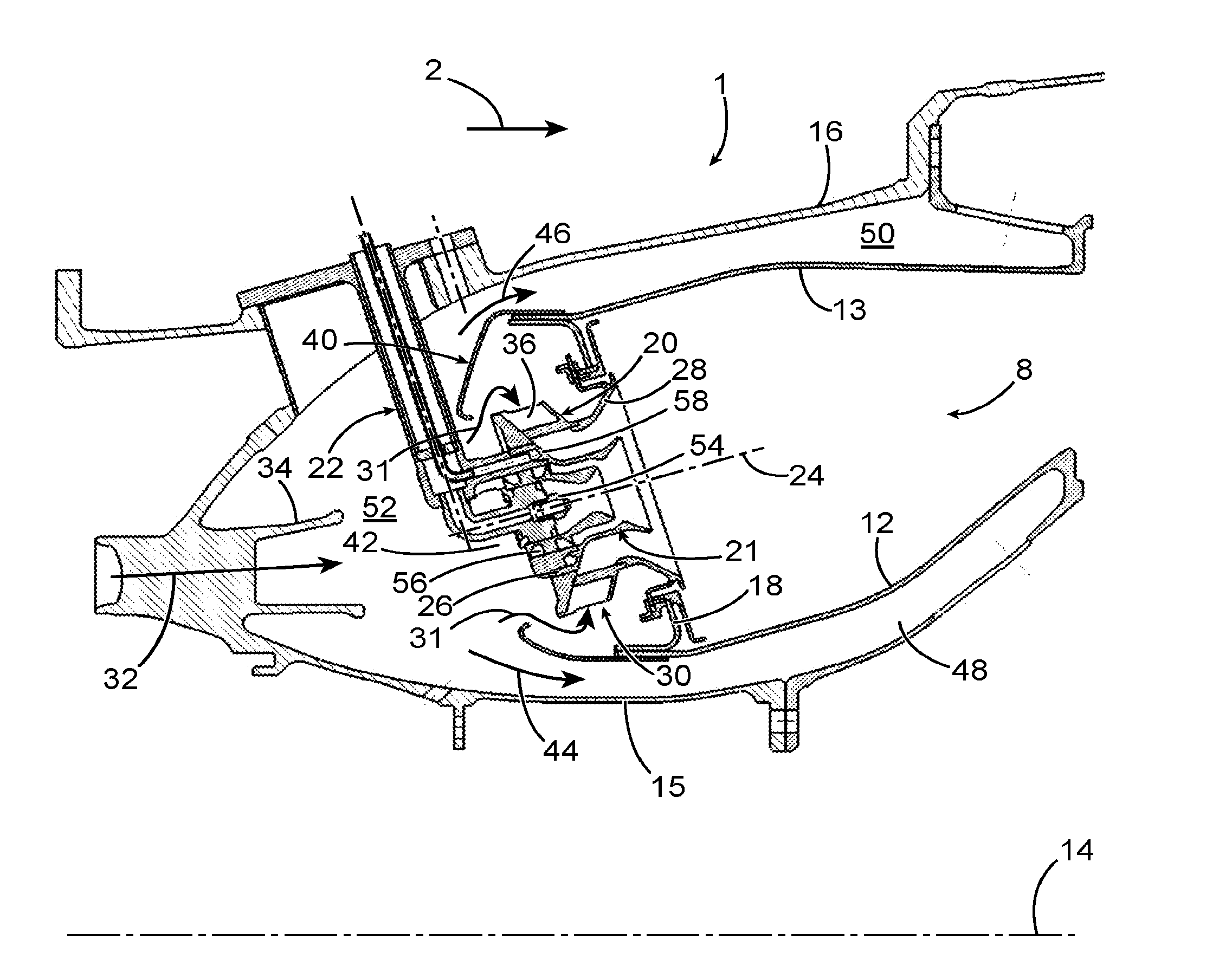
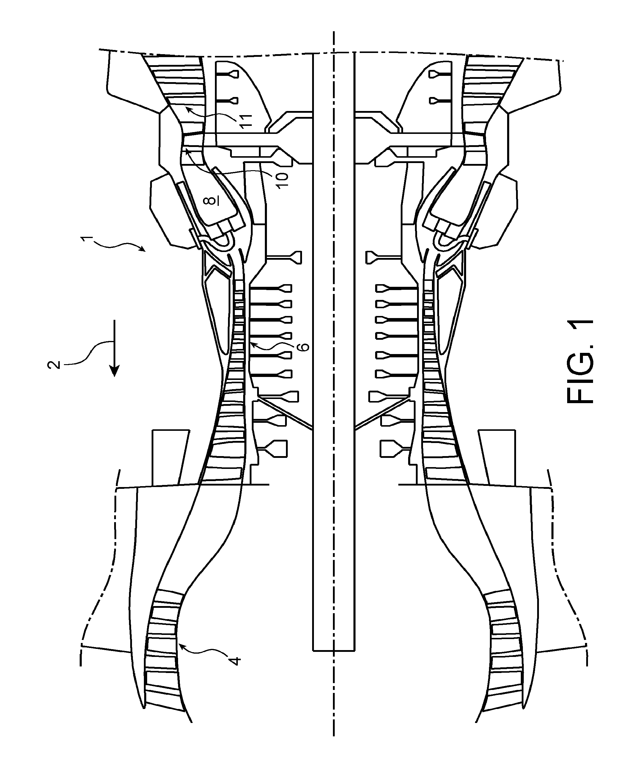
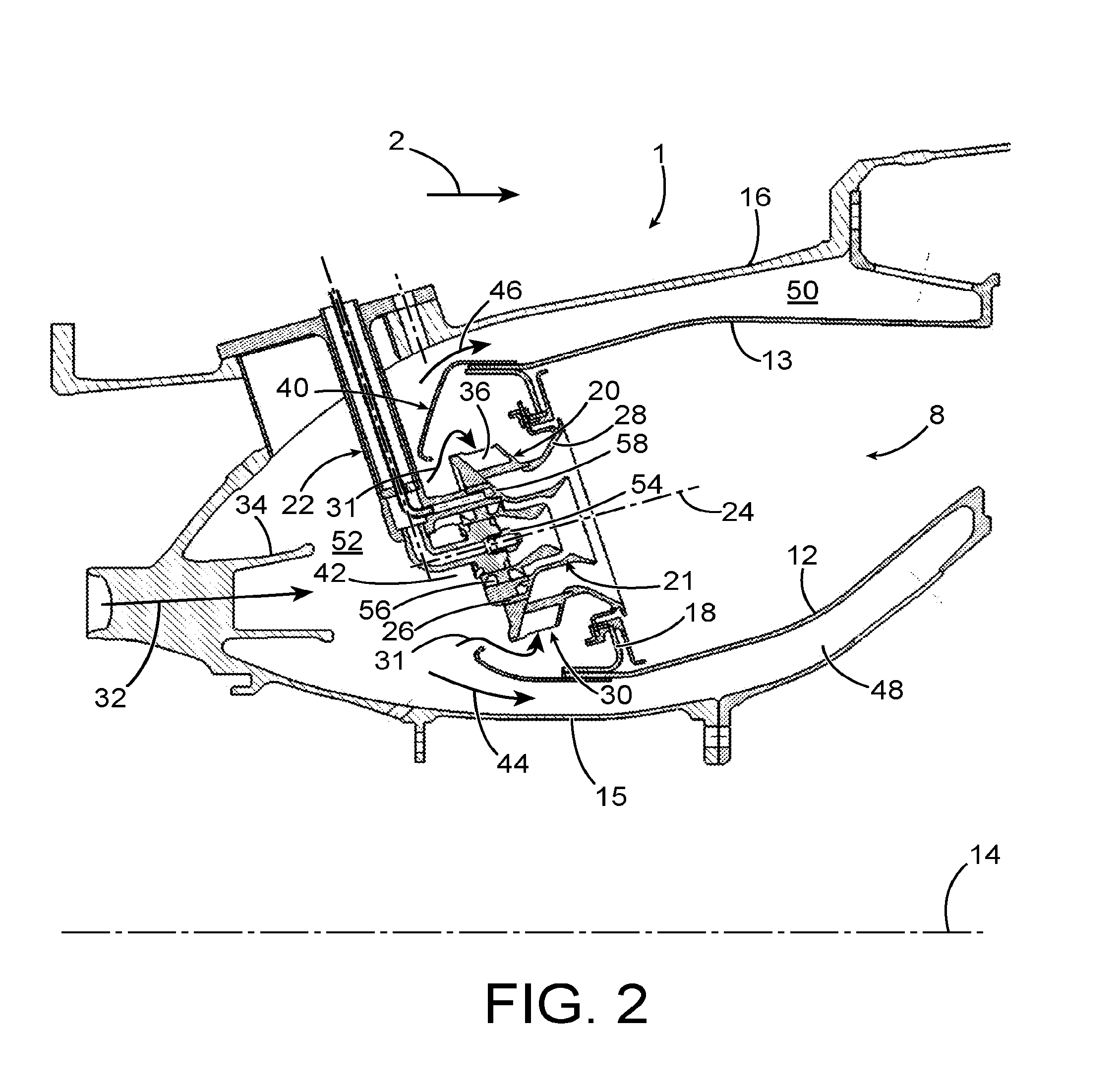
[0050]FIGS. 4 to 6 illustrate part of a combustion chamber module 59 according to a first preferred embodiment of the invention. This combustion chamber module is part of a turbine engine the other parts of which can be of a conventional type, such as illustrated in above-described FIG. 1.

[0051]FIGS. 4 to 6 more particularly show a rear part of the combustion chamber 8 as well as the injectors 22 of the combustion chamber module, whereas FIG. 5 illustrates only the rear part of the combustion chamber 8.

[0052]As appears in FIG. 6, the annular shroud 40′ which covers the upstream side of the combustion chamber 8 includes a plurality of air intake ports 60 separate from the injector ports 42. In the illustrated example, the air intake ports 60 are alternately distributed with the injector ports 42 along the circumference of the annular shroud 40′. In a known manner per se, each injector port 42 is located upstream of the annular air inlet 30 relative to the axis 24 of the corresponding...


PUM


Abstract

A combustion chamber for a turbine engine, including an annular end wall provided with injection systems each centred on a respective axis and each having an upstream end forming a bushing for receiving a head of a fuel injector, and an annular shroud covering the end wall and including injector ports respectively arranged facing the injection systems, wherein the annular shroud includes air intake ports separate from the injector ports, and the bushing of each injection system crosses the corresponding injector port and includes at its upstream end a collar having a free end remote from the axis of the injection system by a first distance greater than a second distance separating a rim of the injector port from the axis.

Description

TECHNICAL FIELD[0001]The present invention relates to an annular combustion chamber for turbine engine, especially for an aircraft propelling assembly.[0002]The invention particularly but not exclusively applies to combustion chambers fitted with an annular row of fuel injectors each comprising a head provided with a central nose for injecting fuel and a peripheral fuel injection device, for example of the multipoint type. Injectors of this type are used in combustion chambers referred to as having “a staged lean combustion”.[0003]The invention also relates to a combustion chamber module and to a turbine engine comprising such a combustion chamber module.STATE OF PRIOR ART[0004]FIG. 1 illustrates a typical example of a turbine engine 1 of a known type, for example an aircraft twin spool turbofan engine.[0005]The turbine engine 1 successively comprises, according to the thrust direction represented by the arrow 2 also corresponding to the general direction of gas flow in the turbine ...

Claims


Application Information

Patent Timeline
IPC IPC(8): F23R3/28F23R3/00F02C7/22F23R3/06
CPCF23R3/28F23R3/06F23R3/002F02C7/222F05D2220/30F05D2240/35F23R3/10F23R3/14F23R3/283F23R3/04
Inventor RULLAUD, MATTHIEU FRANCOISLUNEL, ROMAIN NICOLASNOEL, THOMAS OLIVIER, MARIE
Owner SN DETUDE & DE CONSTR DE MOTEURS DAVIATION S N E C M A
Why Eureka
Try Eureka