Sparsity estimation for data transmission
a data transmission and sparsity technology, applied in the field of sparsity estimation for data transmission, can solve the problems of reducing the energy, bandwidth and storage requirements of the sensor or other electronic device, and achieve the effects of reducing energy, bandwidth and storage requirements, reducing energy requirements, and reducing energy requirements
- Summary
- Abstract
- Description
- Claims
- Application Information
AI Technical Summary
Benefits of technology
Problems solved by technology
Method used
Image
Examples
example environment
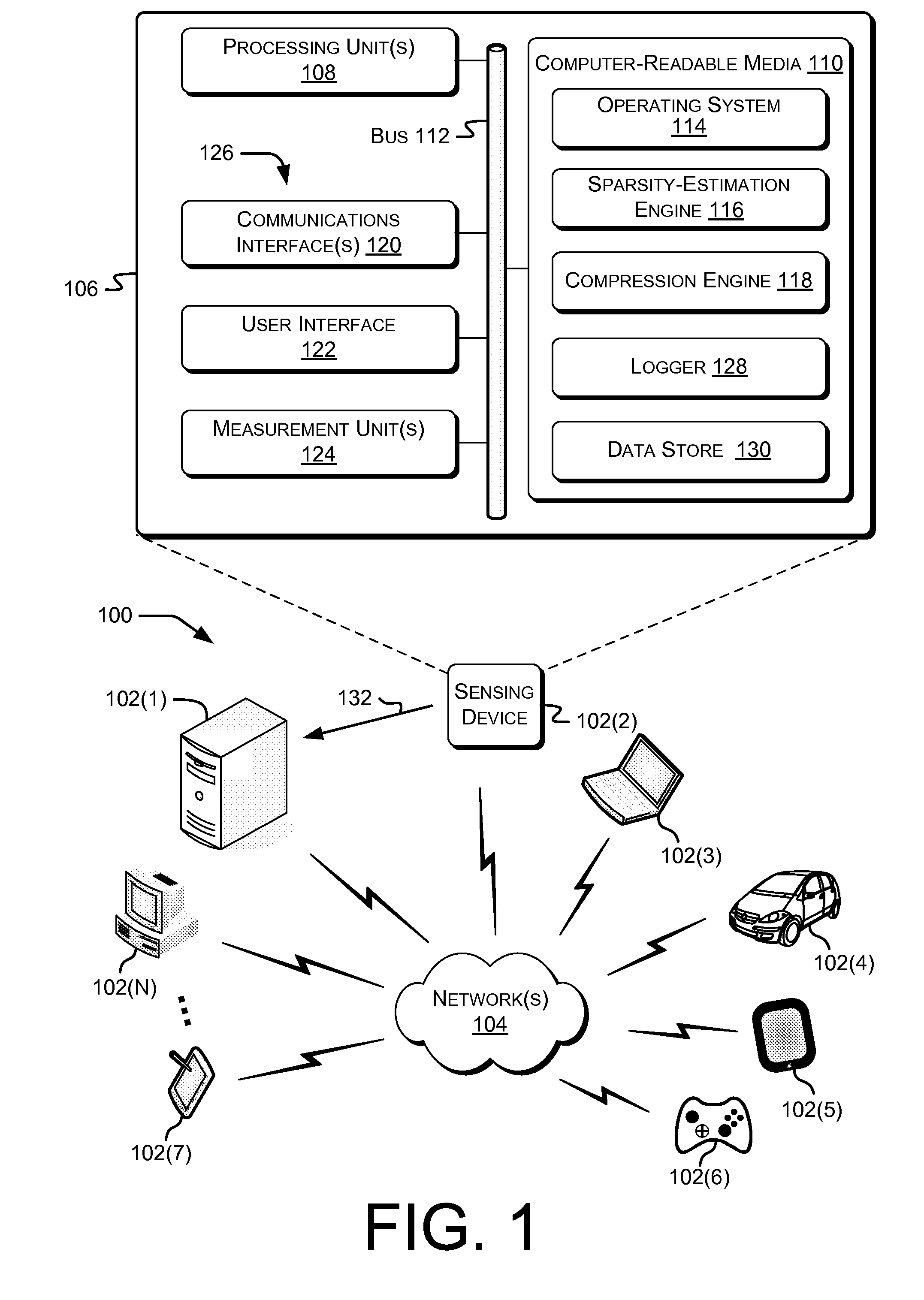
[0018]FIG. 1 shows an example environment 100 in which electronic devices such as sensing devices may operate and in which sparsity-estimation and data-compression methods such as described herein may be performed. FIG. 1 also shows an example computing system usable to perform various methods described herein. In the illustrated example, the various devices and / or components of the environment 100 include electronic device(s) 102(1)-102(N) (e.g., computing devices, sensing devices, or IoT devices, individually or collectively referred to herein with reference 102), where N is any integer greater than or equal to 1. Although illustrated as, e.g., desktop computers, laptop computers, tablet computers, or cellular phones, the electronic device(s) 102 may include a diverse variety of device categories, classes, or types and are not limited to a particular type of device.
[0019]By way of example and not limitation, the electronic device(s) 102 may include, but are not limited to, server ...
example device
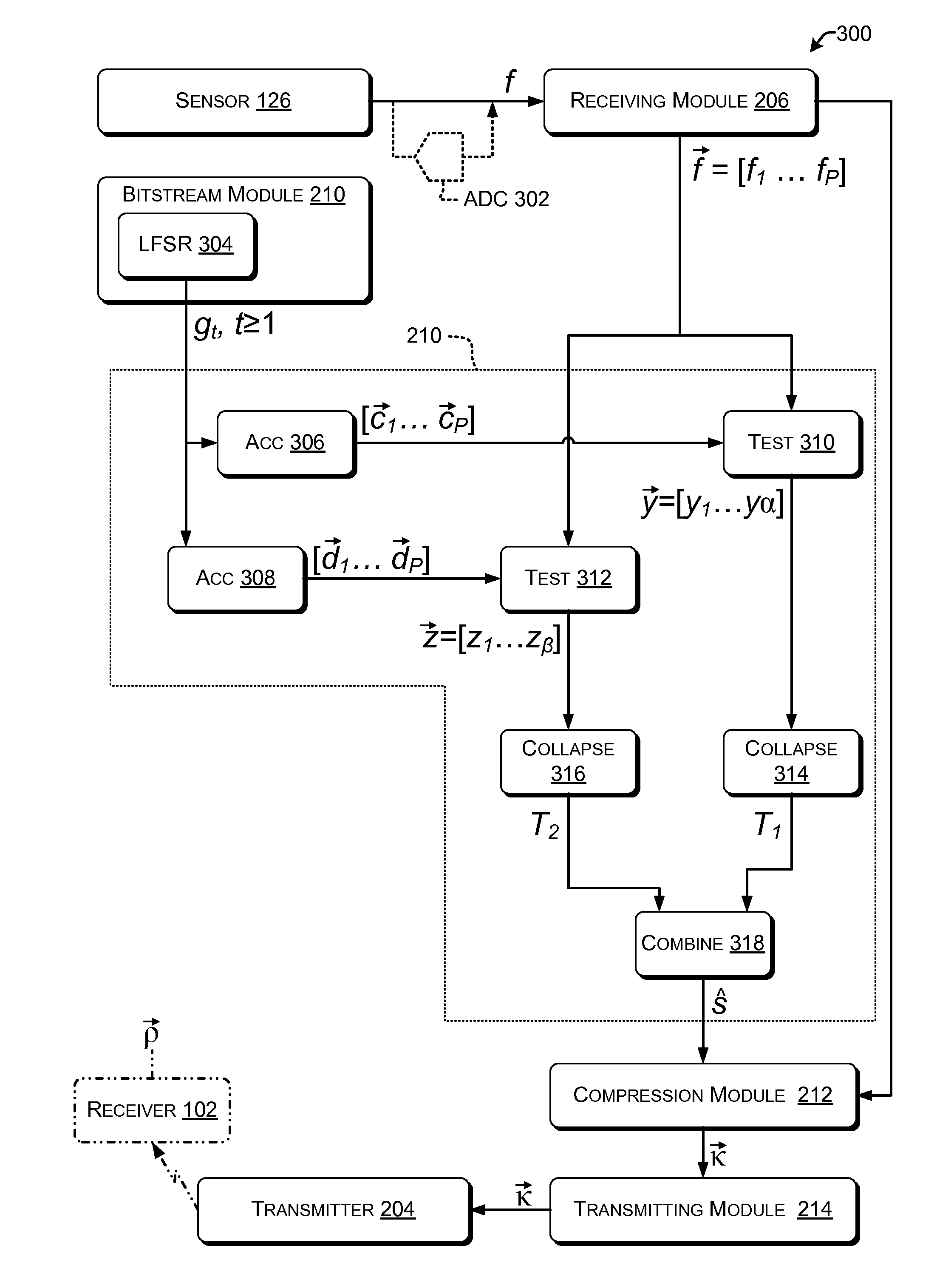
[0083]FIG. 4 illustrates device 400 that implements sparsity-estimation architecture 300 on a specialized integrated circuit or a programmable integrated circuit in accordance with various embodiments. In this figure, “δ” denotes the clock. Flip-flop clock inputs labeled with multiples of δ, e.g., n1δ or n1×δ, signify that the flip-flop is enabled and thus stores a new value once every n1 clock cycles.
[0084]The device 400 includes a bit-sequence generator 402 configured to provide a sequence of bits gt in which each successive bit has a substantially equal probability of being a 0 bit or a 1 bit, e.g., as described above. In the example shown, the bit-sequence generator 402 includes a linear feedback shift register (LFSR). The LFSR includes an arrangement of flip-flops and XOR or exclusive-nor (XNOR) gates configured to provide a pseudorandom bit sequence having p≈0.5 as discussed above. Using an LFSR in bit-sequence generator 402 advantageously provides (pseudo-) random values at m...
example processes
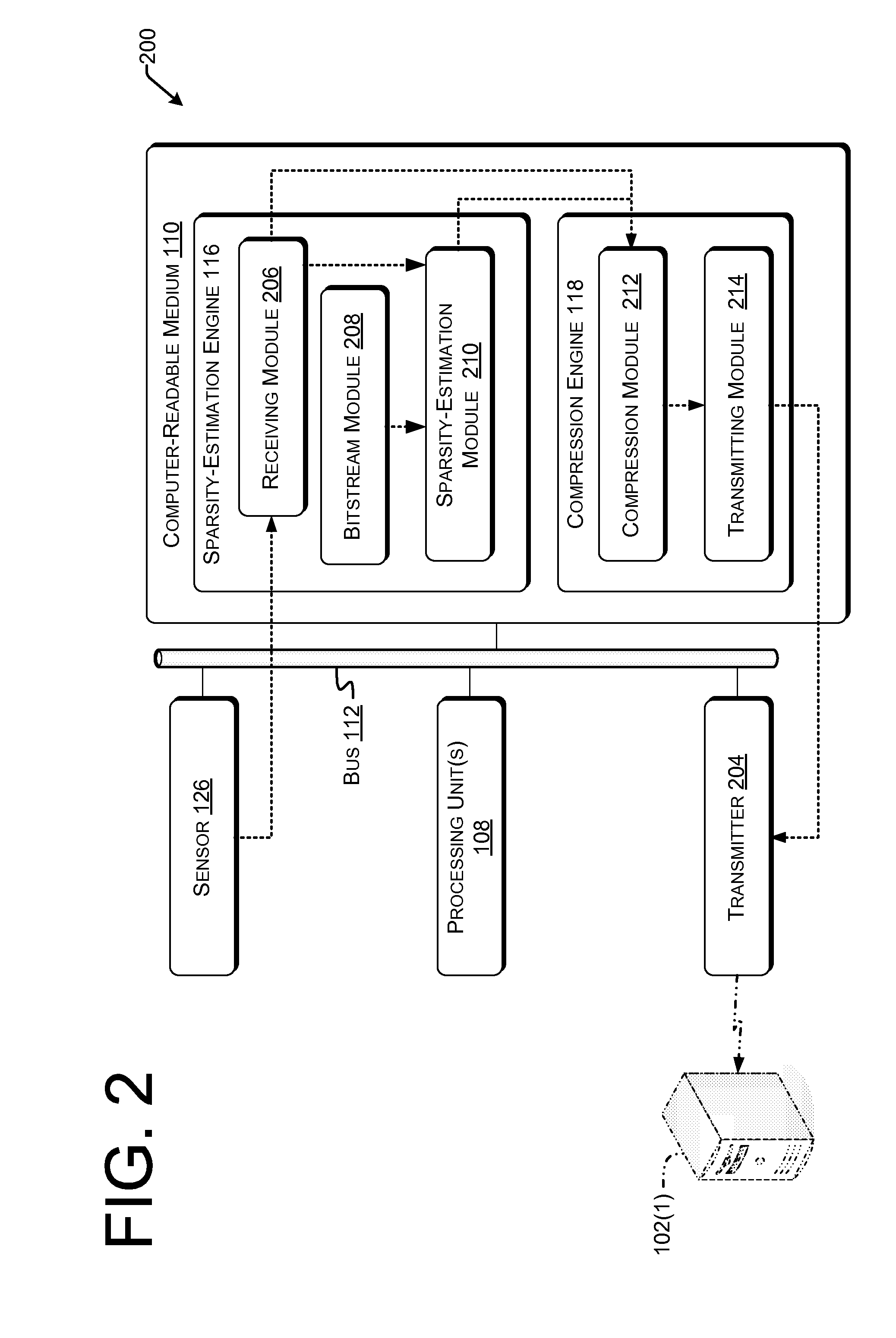
[0100]FIG. 6 depicts a flow graph that shows an example process 600 of compressing data, in accordance with various embodiments. At 602, a plurality of bits may be determined, in which each individual bit has a substantially equal probability of being determined as a 0 bit or of being determined as a 1 bit. This may be done as discussed above with reference to bitstream module 208, FIG. 2. For example, an LFSR or other pseudorandom bit generator can be operated to determine the bits.
[0101]At 604, a sparsity value of data to be compressed may be estimated based at least in part on the plurality of bits. This may be done as described above with reference to sparsity-estimation module 210, FIG. 2. For example, the sparsity value may be estimated by using the determined bits to select values corresponding to statistical distributions such as Cauchy or Gaussian and optionally corresponding to a basis in which the data to be compressed are sparse. These selected values may be combined wit...
PUM
 Abstract
Description
Claims
Application Information
 - R&D
- Intellectual Property
- Life Sciences
- Materials
- Tech Scout
- Unparalleled Data Quality
- Higher Quality Content
- 60% Fewer Hallucinations
Browse by: Latest US Patents, China's latest patents, Technical Efficacy Thesaurus, Application Domain, Technology Topic, Popular Technical Reports.
© 2025 PatSnap. All rights reserved.Legal|Privacy policy|Modern Slavery Act Transparency Statement|Sitemap|About US| Contact US: help@patsnap.com


