
Systems, Devices and Methods for Video Storage

a video storage and video technology, applied in the field of systems, devices and methods for video storage, can solve the problems of affecting random access efficiency, difficult to ensure that the new fragment begins with an i frame, and storage equipment often has a relatively large storage capacity

Active Publication Date: 2016-07-21
HANGZHOU HIKVISION DIGITAL TECH
View PDF3 Cites 5 Cited by
  • Summary
  • Abstract
  • Description
  • Claims
  • Application Information

AI Technical Summary

Benefits of technology

The patent text describes a method for generating buffer zone data in video storage. This data is created through video acquisition and is used to improve video quality and speed up decoding. When a new fragment of the storage area is opened, the method inserts an I Frame with reference to the first frame. This I Frame is the only frame that refers to another frame, called an R Frame. The R Frame is a picture frame that only refers to the I Frame. The method helps to prevent loss of data during storage and avoids cross-storage fragment referencing during reading, resulting in quick decoding with random access.

Problems solved by technology

If a GOP length is overly long, then an average wait time for random access or video playback may be long, which affects the random access efficiency.
Surveillance video often needs to be stored for a relatively long period of time, and thus the storage equipment often has a relatively large storage capacity.
Thus, storing the data in the current buffer zone at this juncture to the new fragment makes it hard to ensure that the new fragment begins with an I Frame.
The conventional approach guarantees that the new fragment begins with the I Frame, but it causes bit stream loss for a period of time.
However, if the time intervals between I Frames in the bit streams output by an encoder are very long (e.g., several minutes or even several hours), the number of frames of a GOP video is very large.
In addition, not all encoders support force-encoding of I Frames.
Therefore, the above-noted conventional approach for video surveillance data storage may be suitable in some circumstances where a GOP length is relatively short, but may not be satisfactory for video surveillance data storage when a GOP length is long.

Method used


Image

  • Systems, Devices and Methods for Video Storage
  • Systems, Devices and Methods for Video Storage
  • Systems, Devices and Methods for Video Storage

Examples


Embodiment Construction

[0033]FIG. 4 is an example computer-implemented environment wherein users 102 can interact with a video storage system 104 hosted on one or more servers 106 through a network 108, according to one embodiment of the present invention. As shown in FIG. 4, the users 102 can interact with the video storage system 104 through a number of ways, such as over one or more networks 108. One or more servers 106 accessible through the network(s) 108 can host the video storage system 104. The one or more servers 106 can also contain or have access to one or more data stores 110 for storing data for the video storage system 104. The one or more servers 106 implement one or more data processors 110. For example, the data processors 110 can be configured for parallel computing.

[0034]The video storage system 104 can assist the users 102 to implement a video data storage algorithm for video surveillance data storage in various circumstances, such as in communities, factories, buildings, military comp...


PUM


Abstract

Systems, devices and methods are provided for video storage. For example, video data is acquired for generating buffer zone data, the buffer zone data beginning with an I frame or an R frame of the video. At least part of the buffer zone data is stored to a storage fragment in a storage area. In response to the storage fragment being newly opened and a first frame of the at least part of the buffer zone data being an R Frame, an I Frame with reference relation to the first frame is inserted to the storage fragment, the R Frame corresponding to a picture frame referring to the I Frame.

Description

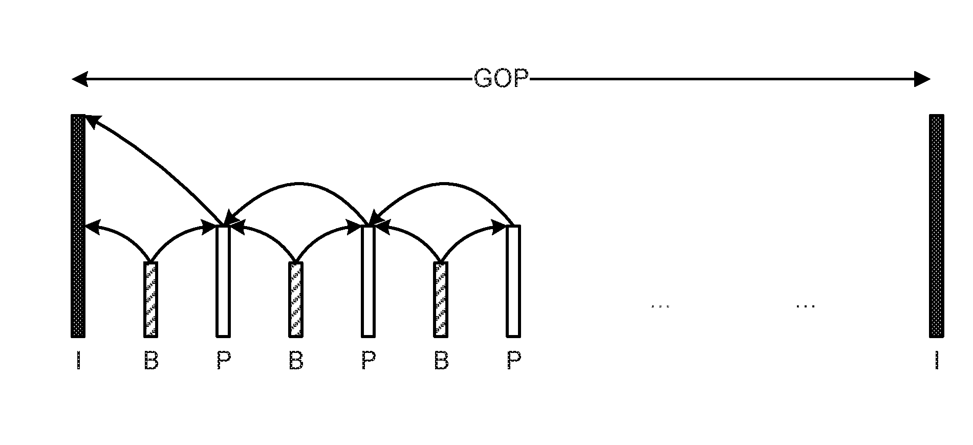
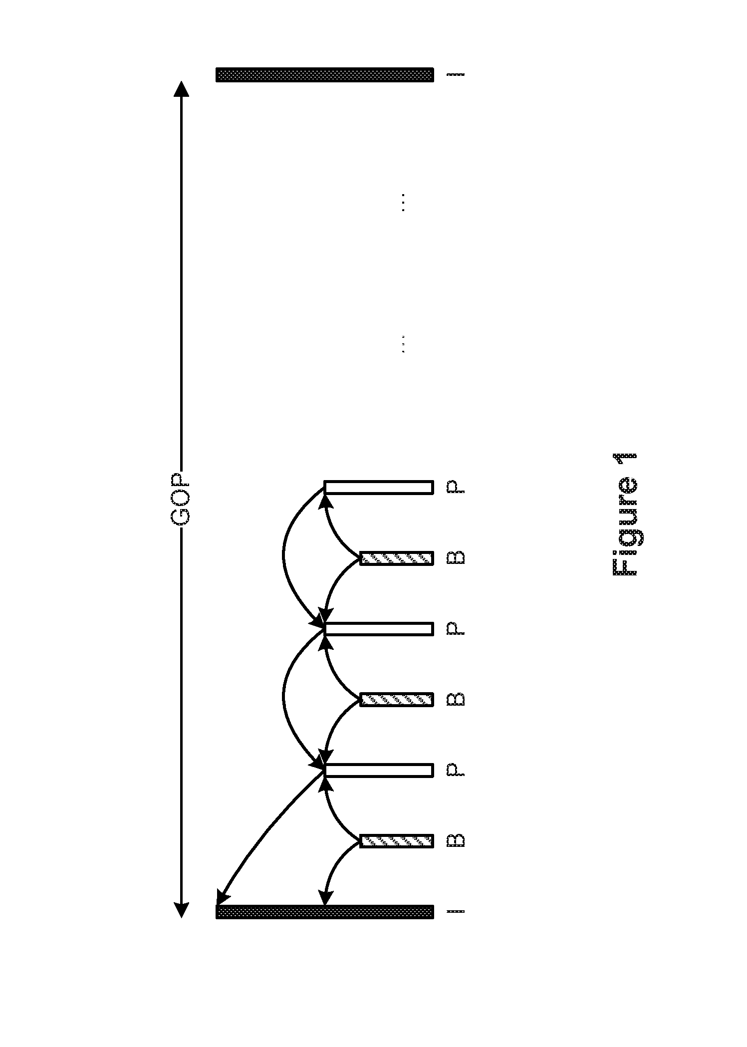
CROSS-REFERENCES TO RELATED APPLICATIONS[0001]The application claims priority to Chinese Patent Application No. 201510024001.4, filed Jan. 16, 2015, incorporated by reference herein for all purposes.BACKGROUND[0002]Video surveillance becomes ubiquitous in modern life, and is used to serve residential security, transportation security, hygiene security, societal security, and production security. For reducing storage costs of large amount of surveillance video or adapting to the need for low bit rate transmission, reduction in encoder bit rates is often sought while good video quality is maintained.[0003]For conventional encoders, encoded frames often include three types of frames: I Frames, P Frames, and B Frames. FIG. 1 is an example diagram showing a reference relationship among the three frame types. An I Frame is an intra encoded frame which has no dependency on other frames, and may be decoded into a complete picture by itself, without reference to any other frames. An I Frame ...

Claims


Application Information

Patent Timeline
IPC IPC(8): G11B27/30G11B20/10G11B20/00G11B27/34G11B27/036
CPCG11B27/3081G11B27/34G11B2020/00072G11B20/00007G11B20/10527G11B27/036G11B27/034H04N19/107H04N19/114H04N19/146H04N19/177H04N21/4334H04N21/00
Inventor CHEN, JIANHUAPU, SHILIANGTAN, XIANGYU, HAI
Owner HANGZHOU HIKVISION DIGITAL TECH
Learn More