
Method and apparatus for testing electronic system

a technology for electronic systems and testing methods, applied in the direction of error detection/correction, instruments, computing, etc., can solve problems such as incomplete consideration, malfunction either immediately, incorrect functional implementation or misunderstanding,

Active Publication Date: 2016-07-21
RANDOMIZE
View PDF12 Cites 16 Cited by
  • Summary
  • Abstract
  • Description
  • Claims
  • Application Information

AI Technical Summary

Benefits of technology

The present invention provides a way to verify the function of a system automatically. It allows the system to be tested in different ways and to transition between states in a random or pseudo-random manner. This helps to speed up the testing process and increase the range of states that can be tested. Overall, this method and device make it easier to verify the function of a system objectively and efficiently.

Problems solved by technology

These problems should rarely propagate to the final product.(2) Syntax or semantic misuse, for example where the coding has been used in a legal way (i.e. it is syntactically correct) but one or more possible implications of the way in which the syntax has been used has not been fully considered.
This may cause a malfunction either immediately or after a period of time.(3) Incorrect functional implementation or misunderstanding.
This may be due to complexity, misunderstandings, simple mistakes or other causes.
Often these sorts of bugs are not at all obvious and only cause problems under unusual or unforeseen combinations of circumstances.
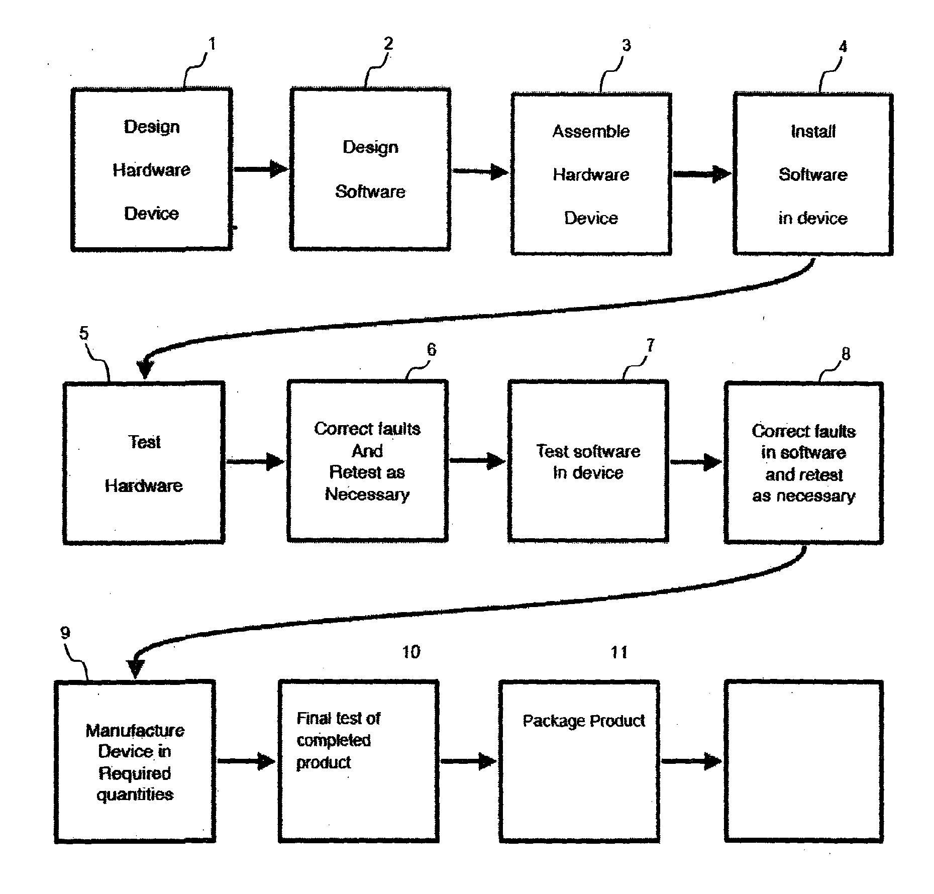
As such electronic systems become increasingly complex, the time and effort that needs to be expended in order to functionally test the equipment increases significantly, and can take a substantial part of the development effort and often the majority of the development effort.
A significant problem is to cover every possible condition or scenario that the design may encounter during operation.
For example, if the operation of the software can be illustrated in the form of a state transition diagram or state diagram where the system transitions from one state to another, the number of states in the entire state space that defines all possible states in which the system may find itself may be so large that only a small number of states may be covered by manually testing the program, and large areas of the state space must necessarily remain uncovered in any manual testing regime with the result that errors and bugs may remain undetected.

Method used


Image

  • Method and apparatus for testing electronic system
  • Method and apparatus for testing electronic system
  • Method and apparatus for testing electronic system

Examples


Embodiment Construction

[0054]To facilitate understanding the structure and operation of the verification software 29, it will be described initially by way of a detailed example, in which the external device 39 shown in FIG. 3 is taken to be a cell phone. However, it should be understood that the invention has wide application and can be used for verifying many different kinds of software controlled systems, devices and apparatus.

[0055]FIG. 4 is a schematic representation of the main components both of the verification software 29 and of the embedded software stored in the memory 40 of the cell phone 39 to be tested and verified. The modules of the verification software 29 are shown in the left-hand portion of the drawing and the modules of the cell phone are shown in the right-hand portion of the drawing. FIG. 4 is drawn in a manner which facilitates understanding the relationship between the modules of the verification software 29 and the functional modules of the cell phone 39.

[0056]The cell phone 39, ...


PUM


Abstract

A verification apparatus and method are disclosed for testing a device or system which is operable in a number of states through which it can transition in a multiplicity of different sequences. The method and apparatus disclosed include a set of functional modules which correspond to the states of the device or system under test and which may be activated in a large number of pseudorandom sequences. Each time a module of the verification apparatus is activated it causes the device or system under test to transition to the corresponding state. Thus, when the functional modules of the verification apparatus are activated in a given sequence, the corresponding states of the device or system under test are called in the same sequence.

Description

FIELD OF THE INVENTION[0001]This invention relates to methods and apparatus for the testing of electronic systems and devices, especially computer controlled digital systems and devices. The invention is particularly applicable to the testing of such systems and devices prior to and during the manufacture thereof so that erroneous operability or functionality can be detected and corrected, thereby enabling the quality and reliability of the manufactured product to be improved.BACKGROUND[0002]Electronics systems which may include both hardware and software components, must be tested or functionally verified in order to ensure, as far as practicable, that they operate correctly under all conceivable circumstances.[0003]Differences between the intended or required functionality of the system and the actual functionality are commonly referred to as “bugs” and may fall into three general categories:[0004](1) Syntax coding errors, i.e. where the coding employed to implement the algorithms...

Claims


Application Information

Patent Timeline
Patent Type & Authority Applications(United States)
IPC IPC(8): G06F11/36
CPCG06F11/3688G06F11/3692G06F11/3684G06F11/3672G06F11/3676G06F7/584
Inventor HALL, GILES THOMAS
Owner RANDOMIZE
Learn More