Liquid Jetting Apparatus

a technology of liquid jetting apparatus and cylinder, which is applied in the direction of printing, etc., can solve the problems of affecting the quality of liquid jetting, so as to achieve a relatively small flexural deformation and shorten the effect of the shortening

Active Publication Date: 2016-07-21
BROTHER KOGYO KK
View PDF2 Cites 1 Cited by
  • Summary
  • Abstract
  • Description
  • Claims
  • Application Information

AI Technical Summary

Benefits of technology

[0009]However, in the ink jet head disclosed in Japanese Patent Application Laid-open No. 2005-22190, it is configured that the ink is supplied to the respective pressure chambers from the manifold formed in the flow passage formation substrate in a planar direction of the substrate. In contrary to this, it is also possible to adopt a configuration of forming liquid supply holes in the vibration film to communicate with the ends of the pressure chambers so as to supply the ink to the respective pressure chambers from a direction orthogonal to the substrate (see FIGS. 2 to 4 which will be explained in an embodiment). However, when the traces are drawn out from the ends of the individual electrodes in the longitudinal direction of the pressure chambers, if the liquid supply holes are arranged in end portions of the pressure chambers on the side of drawing out the traces, then it is necessary to arrange the traces to bypass the liquid supply holes. Because of this, the respective traces become longer, thereby increasing the traces' resistance.
[0010]It is an object of the present teaching to shorten the traces as much as possible while preventing a decrease in the reliability for connecting the individual electrodes and the traces due to the flexural deformation of the vibration film in a configuration in which the liquid supply holes are provided in the vibration film at portions facing the end portions of the pressure chambers on the side in which the traces are drawn out.
[0012]According to the present teaching, the liquid supply holes are formed in the vibration film at portions facing the end portions of the pressure chambers on one side in the second direction (longitudinal direction). Further, the traces are connected to the connecting portions provided in end portions, of the individual electrodes arranged to overlap with the central portions of the pressure chambers, on the one side in the second direction. Further, the traces extend from the connecting portions in the third direction intersecting the second direction, on the one side with respect to the connecting portions of the individual electrodes in the second direction, within the area facing the pressure chambers. In this manner, by drawing out the traces from the connecting portions in the third direction intersecting the second direction, the traces need not he arranged to bypass the liquid supply holes and it is possible to shorten as much as possible the traces before being drawn out to the outer side of the pressure chambers.
[0013]Further if the traces are arranged in an area of the vibration film facing the pressure chambers, then due to a flexural deformation of the vibration film when a voltage is applied to the piezoelectric elements, the traces are displaced vertically to exert a force on the connecting portions of the individual electrodes such that the connecting portions and the traces are liable to be disconnected. In this regard, according to the present teaching, in each area, of the vibration film, on which the trace is arranged, and which is on the one side in the second direction (the longitudinal direction of the pressure chambers) with respect to the connecting portion of the individual electrode, flexural deformation is comparatively small. That is, by arranging the traces in the area where the flexural deformation is comparatively small within the area of the vibration film facing the pressure chambers, it is also possible to secure the reliability in the electrical connection between the connecting portions of the individual electrodes and the traces.

Problems solved by technology

Further if the traces are arranged in an area of the vibration film facing the pressure chambers, then due to a flexural deformation of the vibration film when a voltage is applied to the piezoelectric elements, the traces are displaced vertically to exert a force on the connecting portions of the individual electrodes such that the connecting portions and the traces are liable to be disconnected.

Method used


Image

  • Liquid Jetting Apparatus
  • Liquid Jetting Apparatus
  • Liquid Jetting Apparatus

Examples


Embodiment Construction

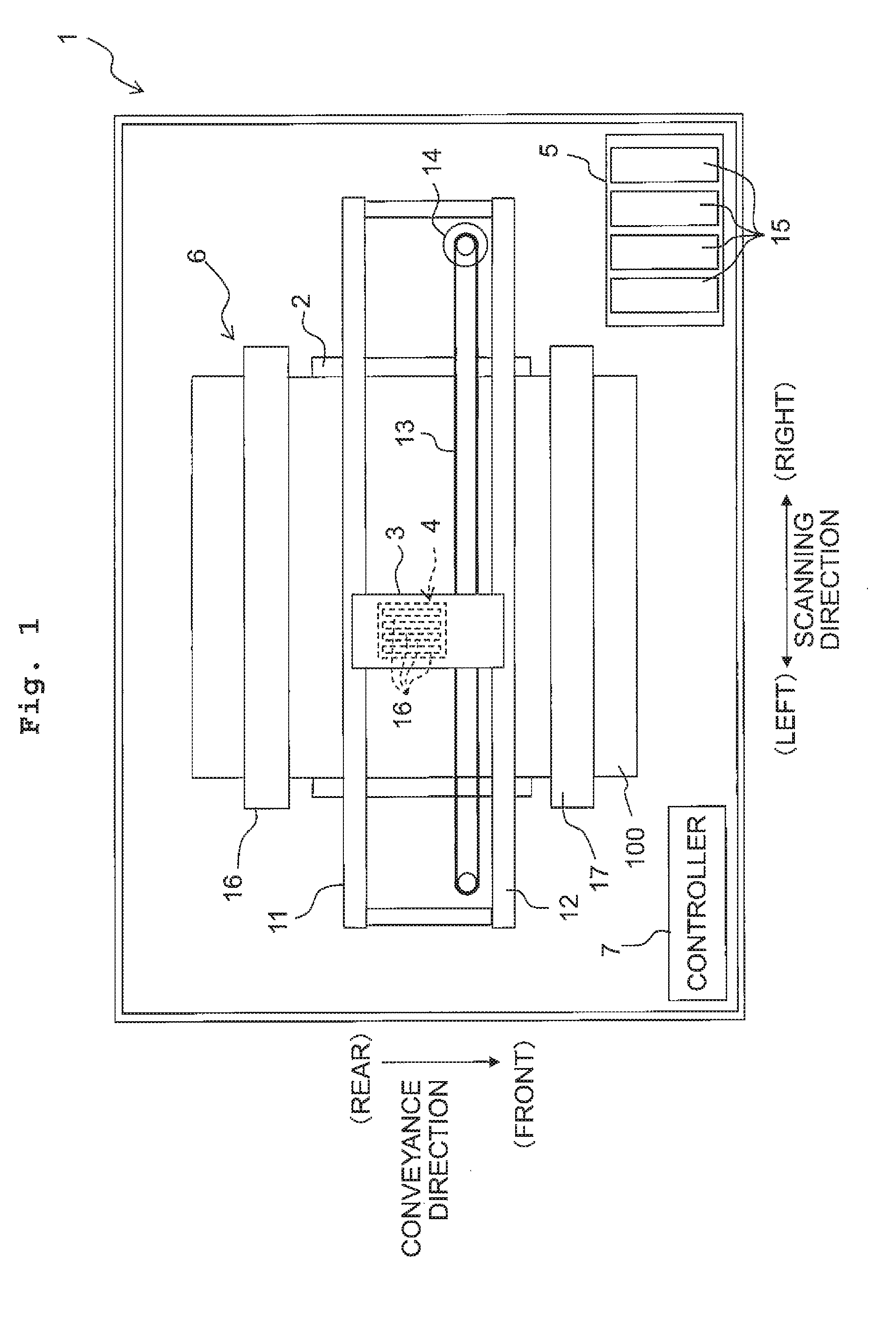
[0024]Next, a preferred embodiment of the present teaching will he explained. FIG. 1 is a schematic plan view of a printer according to the preferred embodiment of the present teaching. Further, the front, rear, left and right directions depicted in FIG. 1 are defined as “front”, “rear”, “left” and “right” of the printer, respectively. Further, the near side of the page of FIG. 1 is defined as “upper side” or “upside”, while the far side of the page is defined as “lower side” or “downside”. The following explanation will be made while appropriately using each directional term of the front, rear, left, right, upside, and downside.

[0025]

[0026]As depicted in FIG. 1, the ink jet printer 1 includes a platen 2, a carriage 3, an ink jet head 4, a cartridge holder 5, a transport mechanism 6, a controller 7, etc.

[0027]On the upper surface of the platen 2, there is carried a sheet of recording paper 100 which is a recording medium. The carriage 3 is configured to be movable reciprocatingly in...


PUM


Abstract

A liquid jetting apparatus includes: a flow passage structure having nozzles aligned in a first direction, pressure chambers aligned in the first direction to correspond respectively to the nozzles, and a vibration film covering the pressure chambers; piezoelectric elements arranged on the vibration film to correspond respectively to the pressure chambers; and traces extending along a planar direction of the vibration film to correspond respectively to the piezoelectric elements. Each of the piezoelectric elements has a piezoelectric film arranged to cover the pressure chambers, and an individual electrode provided on the piezoelectric film to face a central portion of one of the pressure chambers and extending in a second direction intersecting the first direction. Within each area, of the vibration film, facing one of the pressure chambers, each of the traces extends from a connecting portion of the individual electrode along a third direction intersecting the second direction.

Description

CROSS REFERENCE TO RELATED APPLICATION[0001]The present application claims priority from Japanese Patent Application No. 2015-007000 filed on Jan. 16, 2015, the disclosures of which is incorporated herein by reference in its entirety.BACKGROUND[0002]1. Field of the Invention[0003]The present teaching relates to liquid jetting apparatuses jetting liquid.[0004]2. Description of the Related Art[0005]Japanese Patent Application Laid-open No. 2005-22190 discloses an ink jet head as a liquid jetting apparatus which jets ink from a plurality of nozzles respectively. This ink jet head includes a flow passage formation substrate in which a plurality of pressure chambers are formed, a nozzle plate which is joined to the flow passage formation substrate and in which the plurality of nozzles are formed to communicate respectively with the plurality of pressure chambers, and a plurality of piezoelectric elements arranged on the flow passage formation substrate to correspond respectively to the p...

Claims


Application Information

Patent Timeline
Patent Type & Authority Applications(United States)
IPC IPC(8): B41J2/14
CPCB41J2/14233B41J2/14072B41J2002/14491
Inventor HAYASHI, HIDEKIHIRAI, KEITAHIROTA, ATSUSHI
Owner BROTHER KOGYO KK
Why Eureka
Try Eureka